


7K200 SATA OEM Specification
171/173
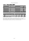
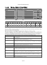
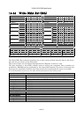
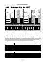
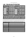
15 Timings
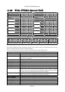
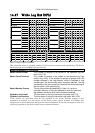
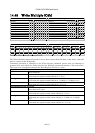
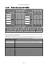
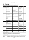
The timing of BSY and DRQ in Status Register are shown in the following table.
The other timings are described in Functional Specification part.
FUNCTION INTERVAL START STOP TIMEOUT
Power On and
COMRESET
Device Ready
After Power On
Power On and COMRESET Status Register
BSY=0 and RDY=1
and sends a Register
FIS to the host.
31 sec
Device Busy
After Software Reset
Device Control Register
RST=1 and sends a Register
FIS to the Device.
Status Register
BSY=1
400 ns Software
Reset
Device Ready
After Software Reset
Device Control Register
RST=0 and sends a Register
FIS to the Device. After
RST=1 and sends a Register
FIS to the Device.
Status Register
BSY=0 and RDY=1
and requests to send a
Register FIS to the host.
31 sec
COMRESET Device Ready
After COMRESET
COMRESET Signal
Asserted
Status Register
BSY=0 and RDY=1
and sends a Register
FIS to the Host.
31 sec
Device Busy
After a Register FIS to issue a
command
Sets proper values in the
registers and sends a Register
FIS
Status Register
BSY=1
400 ns
PIO SETUP FIS for data-in
transfer
Status Register
BSY=1
Status Register
BSY=0 and DRQ=1
and sends a PIO
SETUP FIS to the host.
30 sec
Data In
Command
Device Busy
After Data Transfer In
A PIO SETUP FIS is
transferred to the host.
Status Register
BSY=1
10 us
Device Busy
After a Register FIS to issue a
command
Sets proper values in the
registers and sends a Register
FIS
Status Register
BSY=1
400 ns
Device Busy
After Data Transfer Out
Sends a Data FIS to the device. Status Register
BSY=1
5 us
Data Out
Command
PIO SETUP FIS for data-out
transfer
Status Register
BSY=1
Status Register
BSY=0 and RDY=1
and sends a PIO
SETUP FIS to the host.
30 sec
(Note.1)
Device Busy
After a Register FIS to issue a
command
Sets proper values in the
registers and sends a Register
FIS
Status Register
BSY=1
400 ns
N
on-Data
Command
A Register FIS to report
Command Complete
Status Register BSY=1 Sets the status of the
command to the Status
Register and sends a
Register FIS to the host
30 sec
(Note.2)
DMA Data
Transfer
Command
Device Busy
After a Register FIS to issue a
command
Sets proper values in the
registers and sends a Register
FIS
Status Register
BSY=1
400 ns
Table 138 Timeout Values
Command category is referred to “13 Command Protocol” on page 70.
The abbreviations “ns”, “us”, “ms” and “sec” mean nanoseconds, microseconds, milliseconds and
seconds, respectively.
We recommend that the host system executes Soft reset and then retry to issue the command if
the host system timeout would occur for the device.
(Note.1)
For SECURITY ERASE UNIT command, the execution time is referred to “14.28 Security