


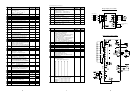
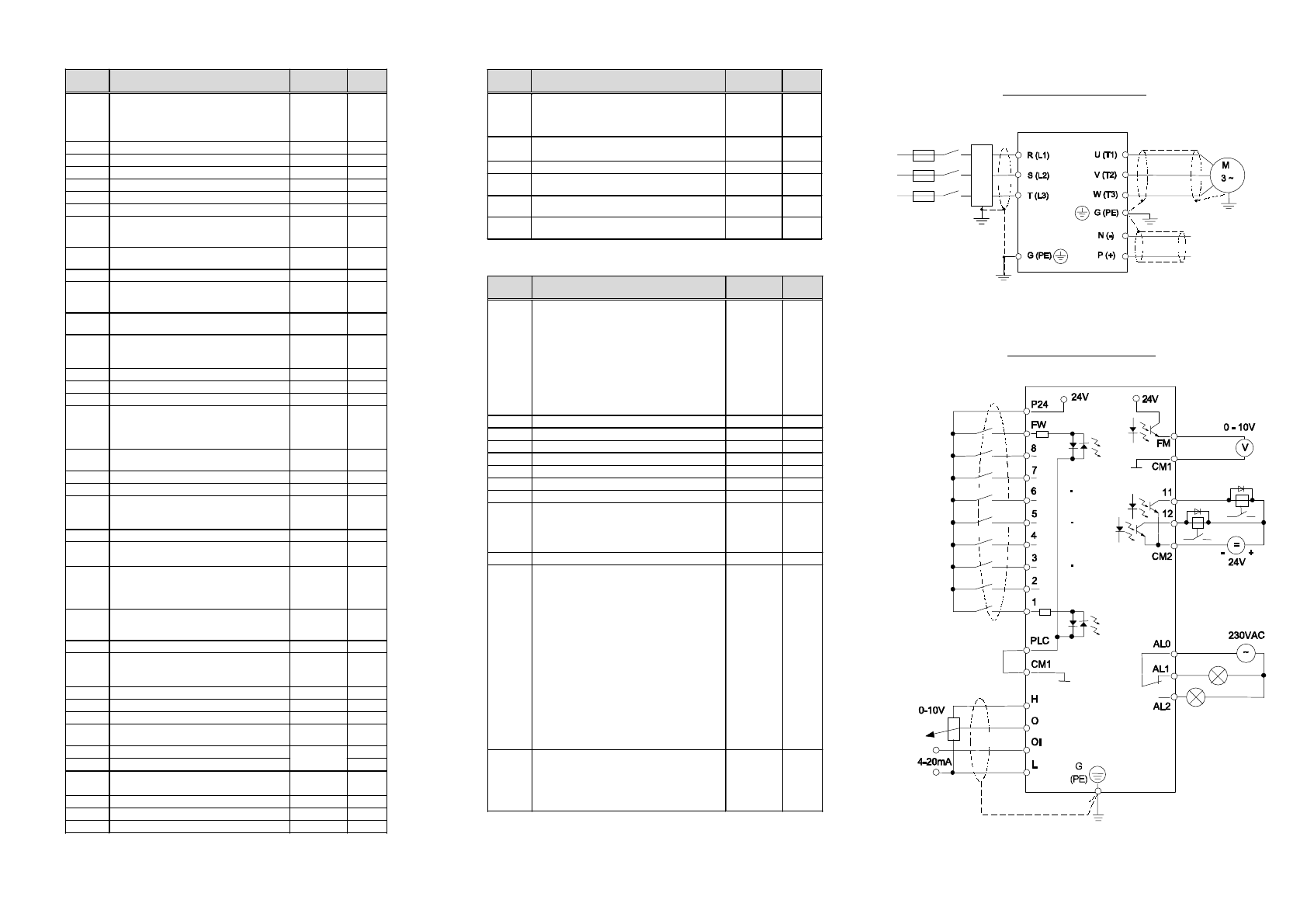
(Continued from previous page)
Di
sp
l
ay
Function
Standard
Setting
Set
Value
A94
PID feedback signal location / I gain setting
0-PID control not active
1-Terminal OI / 1 2-Terminal O / 1
3-Terminal OI / 10 4-Terminal O / 10
0
A95
PID control set value setting
0-Via
A96
1-Via
A 9
0
A96
PID control internal set value (in %) 0
A97
Autotuning mode:
0-Autotuning off
1-Autotuning on 2-Autotuning / static
0
A98
Motor data: 0- Standard Hitachi 1-Hitachi-
special motors 2-Read in motor data
0
A99
Power supply phase breakdown will cause
tri
p
E24
: 0-Yes 1-No
0
Di
sp
l
ay
Function
Standard
Setting
Set
Value
C
0
Function of input terminal 1
0-REV (Reverse run) 1-CF1 (Multispeed 1)
2-CF2 3-CF3 5-JG (Jogging)
6-DB (External DC braking)
7
-
STN (factory setting)8
-
SET (Use 2. setting)
9-CH1 (2. stage acceleration/deceleration)
11-FRS (free run mode)
12
-
EXT (external trip) 13
-
USP (USP function)
14-CS (Motor free run) 15-SFT (Software
lock) 16-AT (Use analog input OI)
18
-
RS (Reset) 27
-
UP (Remote control accele
-
ration
)
2
8
-D
WN
(
Remote control deceleration
)
18
C
1
Function of input terminal 2 (See
C
0
)16
C
2
Function of input terminal 3 (See
C
0
)5
C
3
Function of input terminal 4 (See
C
0
)11
C
4
Function of input terminal 5 (See
C
0
)9
C
5
Function of input terminal 6 (See
C
0
)2
C
6
Function of input terminal 7 (See
C
0
)1
C
7
Function of input terminal 8 (See
C
0
)0
C10
Function of output terminal 11:
0-FA1 (frequency arrival)
1-RUN signal (Motor running)
2-OTQ (torque alarm; only usable when SLV
mode is active)
0
C11
Function of output terminal 12 (See
C10
)1
C20
Digital input type 1-4: Normally open (no)
or Normally closed (nc)
Input1 Input2 Input3 Input 4
00 no no no no
01 nc no no no
02 no nc no no
03 nc nc no no
04 no no nc no
05 nc no nc no
06 no nc nc no
07 nc nc nc no
08 no no no nc
09 nc no no nc
0A no nc no nc
0B nc nc no nc
0C no no nc nc
0D nc no nc nc
0E no nc nc nc
0F nc nc nc nc
08
C21
Digital output type 11, 12 and alarm output:
Normally open (no) or Normally closed (nc)
07 06 05 04 03 02 01 00
Output 11 nc no nc no nc no nc no
Output 12 nc nc no no nc nc no no
Alarm ncncncncnononono
04
Di
sp
l
ay
Function
Standard
Setting
Set
Value
A
0
Characteristic V/F curve setting
0-constant torque
1-M ~ n
1,5
2-M ~ n
1,7
3-M ~ n
2
4-SLV 5-SLV
+
feedback
0
A
1
Motor capacity setting
Cf. nameplate
A
2
Motor poles: 2, 4, 6, 8 4
A
3
ASR constant 2
A
4
Start frequency setting 0.5
A
5
Maximum operating frequency setting 0
A
6
Minimum operating frequency setting 0
A
7
A
8
A
9
Jump frequency setting 0
A10
Carrier frequency (in kHz)
Depends on
model
A11
Time constant of the filter for analog inputs 8
A12
A13
A14
Multispeed frequency setting All are 0
A23
Level of electronic thermal setting (in % of
the inverter rated current)
100
A24
Selection of electronic thermal characteristic
00-Constant torque 01-Reduced torque
02-Freely configurable (using remote)
0
A25
Motor pole count for rpm monitor via
d 1
4
A26
External frequency setting start point 0
A27
External frequency setting end point 0
A34
Selection of restart mode 00-Alarm
01
-
Motor speed match restart /decel to stop
02-Motor speed match restart
03-Start frequency restart after waiting time
0
A38
Rate of use (in %) of the regenerative braking
resistor (00= braking resistor not active)
0
A39
Arri
v
al fre
q
uenc
y
settin
g
for acceleration
(
Hz
)
0
A40
Arrival frequency setting for decelerat. (Hz) 0
A44
Function of FM terminal
00-Frequency 01-Current
02-Torque 03-Frequency (digital)
0
A47
Factor for
d 3
monitor 1
A48
Frequency set value range
0-Range 0-5V 1-Range 0-10V
1
A49
FA1 signal characteristic: output signal ...
0-on arrival of set value
1-above frequencies set via
A39
/
A40
2-on crossing frequencies set via
A39
/
A40
0
A54
Selection of operation when FRS signal is
cancelled: 00-Restart at motor speed
01-Restart at 0 Hz
01
A58
Step count on RV start (0= RV not active) 6
A59
Operating mode:
0-Normal mode 1-Energy saving mode
2-Shortest possible accel./decel.times
0
A61
Jog frequency setting 1.0
A62
Base frequency setting 50
A63
Maximum frequency setting 50
A64
Selection of largest settable frequency
(120Hz, 400Hz)
120
A80
Frequency command adjustment (terminal O)
A81
Fre
q
uenc
y
command ad
j
ustment
(
terminal
O
I
)
Depends on
model
A86
RS terminal reset signal:
0-Rising edge 1-Falling edge
0
A90
P (proportional) gain setting 1.0
A91
I (integral) gain setting 1.0
A92
D (differential) gain setting 1.0
(Table to be continued on next page)
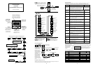
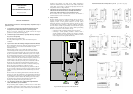
Wiring example: power terminals
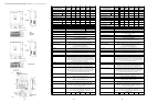
Wiring example: control terminals
Radio noise filter
Power source
External braking
resistor
6 7 8