


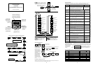
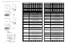
External dimensions and terminal positions part 2/2 (part 1/2 on previous page)
J300-
750 HFE4
900 HFE4
Air
Control
terminals
Main terminals
Wall
Di
g
ital o
p
erator
Air
J300-1100 HFE4
Air
Control
terminals
Main terminals
Wall
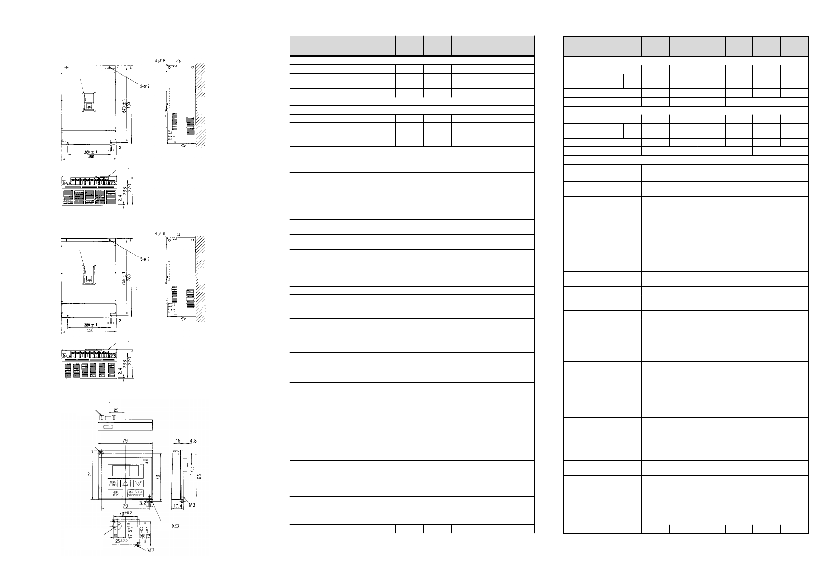
Digital operator
Air
Digital operator
OPE-J
Connector for
extension cable
Cutout for
connector
25m
m
e.g.
Techn
i
cal Spec
i
f
i
cat
i
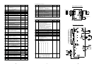
ons
Inverter J300
-
370
HFE4
450
HFE4
550
HFE4
750
HFE4
900
HFE4
1100
HFE4
Loads having constant torque
Maximum motor size in kW 37 45 55 75 90 110
Maximum motor
capacity in kVA
400V 52 62 76 103 122 150
Rated output current in A 75 90 110 149 176 217
Carrier frequency in kHz 2 – 10 2 – 6 2 – 3
Loads having quadratically rising torque
Maximum motor size in kW 45 55 75 90 110 132
Maximum motor
capacity in kVA
400V 61 75 101 122 150 180
Rated output current in A 88 108 146 176 217 260
Carrier frequency in kHz 2 – 4 2
General technical specifications
Protective structure IP00
Rated input voltage Three phase 380 ~ 460V +/-10%, 50/60Hz +/-5%
Rated output voltage Three phase 0 .. 380 ~ 460VAC
(Corresponds to input voltage)
Output frequency range 0,1 ~ 400Hz
Operating principle Sensorless Vector Control (SLV), PWM sine coded.
Power amplifier: IGBT/IPM
Overload current capacity 150% during 60s (constant torque)
115% during 30s (quadratically rising torque)
Frequency accuracy
(at 25°C +/-10°C)
Digital command: +/-0.01% of the maximum frequency
Analog command: +/-0.1% of the maximum frequency
V/F characteristics V/F curves with constant and reduced torque;
vector control without feedback;
vector control with feedback (optional)
Autotuning Automatic adaption to motor characteristics to make
best use of the motor driven
AVR function Automatic Voltage Regulation usable
Acceleration/Deceleration 2 times settable between 0.01 and 3000s (using digital remote
control); linear, S-curve, U-curve
Starting torque 150% at 1Hz (constant torque)
Braking resistor Models J300-055HFE4 and J300-075HFE4 have a built-in braking
resistor. Braking torque approx. 50% to 60% of the rated torque
using the built
-
in braking resistor (the rest of the J300
-
models have
a braking torque of approx. 10% to 15% of the rated torque using
braking with feedback to capacitor).
DC braking Variable operating frequency, time, and braking force.
Frequency command Digital command using the built-in digital operator keys.
Analog 0–5V and 0–10V (input impedance 30kOhm) and
4–20mA (input impedance 250Ohm); optional digital input
Intelligent digital inputs 8 inputs configurable as: Forward run, Reverse run, Free run mode,
Reset, Jog, 7 multistage speed settings, Ext. DC braking, 2. Setting,
2. Stage accel/decel, External alarm, USP function, Software lock,
frequency command from analog input O or OI, Motor poten-
tiometer, Motor free run, Factory setting, etc.
Outputs Analog output current, output frequency, and torque.
Transistor output with signals for frequency arrival, motor
running, torque alarm; Alarm output
Other functions Optimized acceleration and deceleration times using fuzzy logic,
engergy saving mode, electronic thermal, jump frequency,
upper/lower limits, PID control, etc.
Protective functions Overcurrent, overvoltage, undervoltage, overload, excessive
temperature, ground fault, braking resistor overload, etc.
Directives and standards CE-EMC directive in conjunction with optional radio noise
filter and installation according to installation guidelines;
CE low voltage directive
Operating environment Ambient temperature: -10~50°C with constant torque
and -10~40°C with quadratically rising torque.
Humidity: 20-90% RH (non condensing); Installation altitude:
1000m or less
Overall weight (approx.) 364646707080
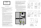
Techn
i
cal Spec
i
f
i
cat
i
ons
Inverter J300
-
055
HFE4
075
HFE4
110
HFE4
150
HFE4
220
HFE4
300
HFE4
Loads having constant torque
Maximum motor size in kW 5.5 7.5 11 15 22 30
Maximum motor
capacity in kVA
400V 9.0 11 16 22 33 40
Rated output current in A 13 16 23 32 48 58
Carrier frequency in kHz 2 – 16 2 – 12 2 – 10
Loads having quadratically rising torque
Maximum motor size in kW 7.5 11 15 22 30 37
Maximum motor
capacity in kVA
400V 11 16 22 30 41 51
Rated output current in A 16 23 32 44 59 74
Carrier frequency in kHz 2 – 8 2 – 4
General technical specifications
Protective structure IP20 IP00
Rated input voltage Three phase 380 ~ 460V +/-10%, 50/60Hz +/-5%
Rated output voltage Three phase 0 .. 380 ~ 460VAC
(Corresponds to input voltage)
Output frequency range 0,1 ~ 400Hz
Operating principle Sensorless Vector Control (SLV), PWM sine coded.
Power amplifier: IGBT/IPM
Overload current capacity 150% during 60s (constant torque)
115% during 30s (quadratically rising torque)
Frequency accuracy
(at 25°C +/-10°C)
Digital command: +/-0.01% of the maximum frequency
Analog command: +/-0.1% of the maximum frequency
V/F characteristics V/F curves with constant and reduced torque;
vector control without feedback;
vector control with feedback (optional)
Autotuning Automatic adaption to motor characteristics to make
best use of the motor driven
AVR function Automatic Voltage Regulation usable
Acceleration/Deceleration 2 times settable between 0.01 and 3000s (using digital remote
control); linear, S-curve, U-curve
Starting torque 150% at 1Hz (constant torque)
Braking resistor Models J300-055HFE4 and J300-075HFE4 have a built-in braking
resistor. Braking torque approx. 50% to 60% of the rated torque
using thebuilt
-
inbraking resistor (the rest ofthe J300
-
modelshave
a braking torque of approx. 10% to 15% of the rated torque using
braking with feedback to capacitor).
DC braking Variable operating frequency, time, and braking force.
Frequency command Digital command using the built-in digital operator keys.
Analog 0–5V and 0–10V (input impedance 30kOhm) and
4–20mA (input impedance 250Ohm); optional digital input
Intelligent digital inputs 8 inputs configurable as: Forward run, Reverse run, Free run mode,
Reset, Jog, 7 multistage speed settings, Ext. DC braking, 2. Setting,
2. Stage accel/decel, External alarm, USP function, Software lock,
frequency command from analog input O or OI, Motor poten-
tiometer, Motor free run, Factory setting, etc.
Outputs Analog output current, output frequency, and torque.
Transistor output with signals for frequency arrival, motor
running, torque alarm; Alarm output
Other functions Optimized acceleration and deceleration times using fuzzy logic,
engergy saving mode, electronic thermal, jump frequency,
upper/lower limits, PID control, etc.
Protective functions Overcurrent, overvoltage, undervoltage, overload, excessive
temperature, ground fault, braking resistor overload, etc.
Directives and standards CE-EMC directive in conjunction with optional radio noise
filter and installation according to installation guidelines;
CE low voltage directive
Operating environment Ambient temperature: -10~50°C with constant torque
and -10~40°C with quadratically rising torque.
Humidity: 20-90% RH (non condensing); Installation altitude:
1000m or less
Overall weight (approx.) 7.5 7.5 13 13 21 36
12 13 14