


SJ100/L100 / PID / 8
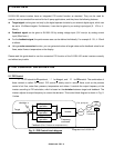
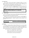
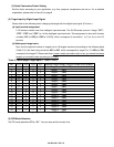
(3) Deviation Calculation
Every calculation in PID control in the SJ100/L100 is based on “%” so that it can be used with
various applications and units of measure, such as pressure (N/m
2
), flow (m
3
/min), temperature (degrees)
and so on. For example, comparing target value and feedback value is based on % of target and % of
feedback full scale value.
However, there is a useful function called scale conversion function (A75). If you use this function,
you can set a target value and/or you can monitor target and feedback value in the actual units of the
specific application. Also, there is a “active range of PID” setting function (A11 - A14), which allows you to
define an area based on the feedback signal. Please refer to Fig.3-2 and Fig.3-3 for more detail.
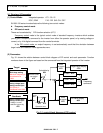
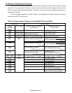
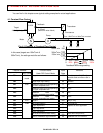
(4) Target Input
Only one source for the target input can be chosen from the following:
l Keypad/Operator (Integrated operator, or DOP, or DRW)
l 4 bits of digital input from the control terminals
l Analog input terminals (O-L terminal or OI-L terminal)
In the case of digital input of the target value from the terminals, it is necessary beforehand to set the
required target values in functions A21 to A35. This allows you to define an array of target values. Then
you can select the one you require from that array according to the combination of the 4 bits of digital input
(binary). This is the same philosophy used for multi-stage speed control in the frequency control mode.
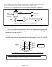
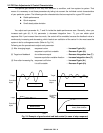
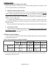
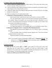
(5) Feedback Input & Setting PID Performance Area
Feedback signals should be given to one of the following units:
l Analog voltage input terminal (O terminal : 10V maximum)
l Analog current input terminal (OI terminal : 20mA maximum)
Select one of them using “Feedback input method selection [A76]”.
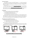
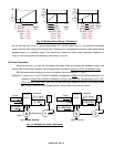
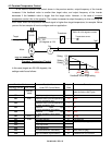
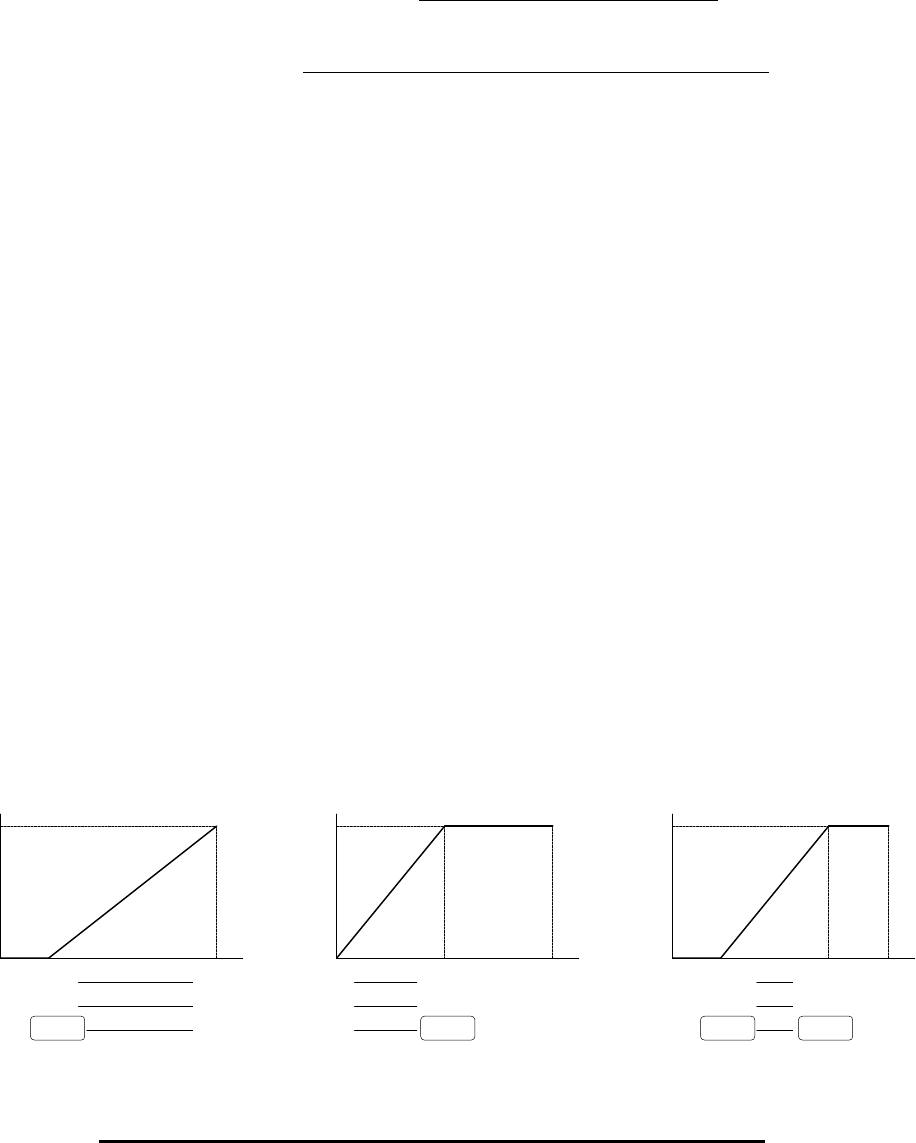
This feedback signal can be defined as shown in Fig.3-2 and Fig.3-3 below, so that you can achieve
suitable performance for your particular system. The “100%” shown at vertical axis is a maximum value
which is based on an internal calculation.
Fig. 3-2 Setting Active Range (A11=0, A12=0 or 100) : Example 1
100
%
0
10V2V0
20mA
(c) A13 = 25%
A14 = 75%
(a) A13 = 20%
A14 = 100%
(b) A13 = 0%
A14 = 50%
4mA0
100%20%0
100
%
0
10V5V0
20mA10mA0
100%50%0
100
%
0
10V2.5V0
20mA5mA0
100%25%0
7.5V
15mA
75%