


10/10/03
CHAPTER 4 HP-GL/2 - 30
7.5. Plot Function Instructions
Instruction Function
AC Anchor Corner
FT Fill Type
LA Line Attribute
LT Line Type
PW Pen Width
RF Raster Fill Definition
SM Symbol Mode
SP Select Pen
SV Screened Vectors
TR Transparency Mode
UL User-defined Line Type
WU Select Unit for Pen Width
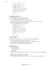
AC - Anchor corner
AC [ X, Y ] [;]
X ; x-coordinate of starting point of fill pattern
Y ; y-coordinate of starting point of fill pattern
•
This command specifies the anchor corner which is the starting position of a fill pattern.
• If no parameters are specified the lower left hand corner of the PCL picture frame, according to the current
coordinate system, becomes the anchor position. This is equivalent to AC0,0;
• User units or graphics units may be used.
• The value of the coordinates are real numbers in the range (-2
30
)
to 2
30
- 1.
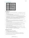
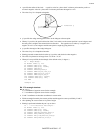
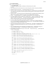
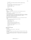
10 '-Anchor Corner -
20 WIDTH "LPT1:",255
30 LPRINT CHR$(27); "E";
40 LPRINT CHR$(27); "%0B";
50 LPRINT "IN;SP1;";
60 LPRINT "PA3000,3000;FT3,400,45;"
70 LPRINT "RR1000,1000;ER1000,1000;"
80 LPRINT "PR1000,0;FT4,400,45;"
90 LPRINT "RR1000,1000;ER1000,1000;"
100 LPRINT "PR1000,0;FT3,400,45;"
110 LPRINT "RR1000,1000,ER1000,1000;"
120 LPRINT "PA3000,1500;AC3000,1500;"
130 LPRINT "RR1000,1000;ER1000,1000;"
140 LPRINT "PA4000,1500;AC4000,1500;FT4,400,45;"
150 LPRINT "RR1000,1000;ER1000,1000;"
160 LPRINT "PA5000,1500;AC5000,1500;FT3,400,45;"
170 LPRINT "RR1000,1000;ER1000,1000;"
180 LPRINT CHR$(27); "%0A";
190 LPRINT CHR$(27); "E";
200 END
<Sample 38>