


10/10/03
CHAPTER 2 "PCL" - 77
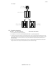
6.3.5. Set raster area height
Esc*r#T (27)(42)(114)#(84) <1Bh><2Ah><72h>#<54h>
• This command sets the height of the raster image to be printed.
• # is the number of raster rows.
• If you use this command after using a Start Raster Graphics or a Transfer Raster Data command, it does not
take effect until after the next End Raster Graphics command.
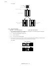
6.3.6. Set raster area width
Esc*r#S (27)(42)(114)#(83) <1Bh><2Ah><72h>#<53h>
• This command sets the width of the raster image to be printed.
• # is the number of dots at the specified dots per inch resolution.
• If you use this command after using a Start Raster Graphics or a Transfer Raster Data command, it does not
take effect until after the next End Raster Graphics command.
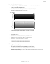
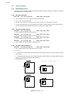
6.3.7. Set raster y-offset
Esc*b#Y (27)(42)(98)#(89) <1Bh><2Ah><62h>#<59h>
• This command sets the offset (number of blank rows to be skipped) for the raster image to be printed.
• # is the number of rows that are left blank at the top of the image.
• # must be in the range 0-32767.
• This command is only effective in raster graphics mode, that is, after a Start Raster Graphics mode
command.
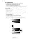
6.3.8. Set compression mode
Esc*b#M (27)(42)(98)#(77) <1Bh><2Ah><62h>#<4Dh>
Identifies the method of compression used to encode the raster image that is to be sent to the printer.
• # is 0, 1, 2, 3, 5, 9, 1152 or 1024.
• # = 0 signifies no compression is to be used.
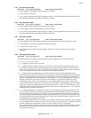
• # = 1 indicates that run-length encoding is to be used. The raster data bytes are transmitted in pairs. The
second byte of each pair specifies the raster output, the first byte specifies the number of times the second
byte is successively repeated. A value of 0 for the first byte indicates a single occurrence of the second byte,
a value of 1 indicates two consecutive occurrences of the second byte and so on.
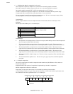
• # = 2 indicates that TIFF (tagged image file format) encoding is to be used. In this format the data is
transmitted in groups of bytes. The first byte of each group is a control byte and defines how the subsequent
data byte or bytes should be interpreted, and how many data bytes there are before the next control byte. If
the two’s complement value of the control byte is in the range –1 to –127, the following byte is a repeated
data byte. The number of successive occurrences of the data byte is given by the absolute value of the
control byte plus one - that is, if the control byte is -6, the following data byte is repeated 7 times. If the
value of the control byte is in the range 0-127 the bytes which follow are unencoded raster data. The number
of data bytes is given by the absolute value of the control byte plus one - that is, if the control byte is 9, the
following ten bytes are unencoded data. If a control byte has the two’s complement value –128 it is ignored
and the next byte is treated as a control byte.
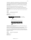
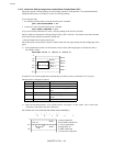
• # = 3 indicates that delta row compression is to be used. In this method byte sequences identify how each
raster row differs from the last row that was transmitted. The first byte identifies the number of consecutive
bytes (the value of the most significant 3 bits plus 1) to be changed and the position in the line at which to
start substituting the replacement bytes (the least significant 5 bits plus 1). Hence, if the command byte has a
3 in the top three bits and 10 in the bottom five bits, the 11th, 12th, 13th and 14th bytes of the last row will
be replaced by the four data bytes that follow.
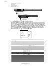
If the least significant 5 bits are all 1, the next byte is treated as a further offset value and its value is added to
32 to calculate the offset. If this byte in turn is all ones the next byte is also treated as a continuation byte and
its value is added to the offset and so on until a byte whose value is not 255 is encountered.
This combination of command bytes and replacement bytes is used to specify all the differences between the
last raster row sent (the seed row) and the new row to be transmitted. When the new row has been sent it
becomes the new seed row.