


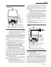


8. Lower the switch assembly into place and tighten
the two mounting screws, making sure the switch follow-
ers are properly aligned with the inner and outer cams in
the motor. The 220736A includes only the switch for the
outer cam.
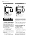
9. Run all switch leadwires through slots to line volt-
age section (at auxiliary end of motor), where connections
to auxiliary equipment should be made with solderless
connectors.
!
CAUTION
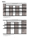
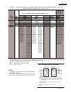
The auxiliary switches in the Series 91 low and
medium torque TRADELINE Modutrol IV Mo-
tors operate opposite to those in the Modutrol
motors listed in Tables 1 and 2, page 4. When
wiring the switches, connect the new switches to
the controlled equipment as shown in the appro-
priate table.
3 63-2228—2
220736A,B
INSTALLATION
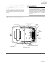
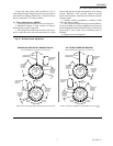
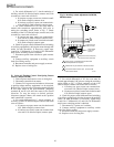
Fig. 1—Position of auxiliary switch(es) in motor.
INTERNAL
AUXILIARY
SWITCH KIT
INNER CAM
POWER
END
OUTER CAM
M 455D
SLOTS (ROUTING SWITCH LEADWIRES
TO LINE VOLTAGE SECTION)
LINE VOLTAGE SECTION
MODUTROL IV WIRING BOX
VOLTAGE BARRIER
TRANSFORMER
(CAN BE FIELD - ADDED)
RIGHT
SWITCH
FOLLOWER
LEFT
SWITCH
FOLLOWER