


7. Check for proper switch differential and switching
of auxiliary equipment by driving the motor through full
stroke (in both directions) using the potentiometer. If
necessary repeat steps 5 and 7 for 1° differential, or 6 and
7 for 10° differential until correct switching action is
obtained.
8. Turn off power and disconnect potentiometer.
9. Connect auxiliary equipment to auxiliary switch
leads. See Wiring section.
10. Reconnect controller and power supply to motor.
11. Replace cover of wiring box. Turn on power.
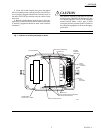
C) High and Extra High Torque, Series 91 Modulat-
ing (Proportional) Motors (M9184, M9185, M9194):
1. Turn off power and remove cover of wiring box.
2. Disconnect controller from motor.
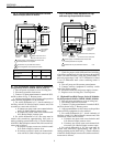
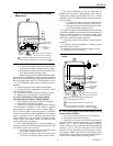
3. Connect 135 ohm potentiometer to terminals R,W,
and B as shown in Fig. 5. Restore power.
4. Adjust potentiometer to drive motor to the position
where auxiliary equipment is to be switched.
5. For switch differential of 1°, check continuity of
auxiliary switch N.O. (Red to Purple) contacts and, with
screwdriver, rotate cam as follows:
a. If contacts are open, rotate cam clockwise until
N.O. (Red to Purple) contacts close.
b. If contacts are closed, rotate cam counterclock-
wise until N.O. (Red to Purple) contacts open.
6. For switch differential of 10°, the cams must be
rotated with screwdriver approximately 180° prior to
setting switching action. Refer to Fig. 3. Check continuity
of the N.O. (Red to Purple) contacts and, with screwdriver,
rotate cam as follows:
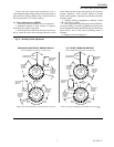
Fig. 4—Auxiliary switch adjustment for low and
medium torque, Series 91 motors.
Fig. 5—Auxiliary switch adjustment for high
and extra high torque Series 91 motors.
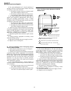
B) Low and Medium Torque, Series 91 Modulating
(Proportional) Motors (M9164, M9174, M9175):
1. Turn off power and remove cover of wiring box.
2. Disconnect controller from motor.
3. Connect 135 ohm potentiometer to terminals R,W,
and B as shown in Fig. 4. Restore power.
4. Adjust potentiometer to drive motor to the position
where auxiliary equipment is to be switched.
5. For switch differential of 1°, check continuity of
auxiliary switch N.O. (Red to Purple) contacts and, with
screwdriver, rotate cam as follows:
a. If contacts are open, rotate cam counterclockwise
until N.O. (Red to Purple) contacts close.
b. If contacts are closed, rotate cam clockwise until
N.O. (Red to Purple) contacts open.
6. For switch differential of 10°, the cams must be
rotated with screwdriver approximately 180° prior to
setting switching action. Refer to Fig. 3. Check continuity
of the N.O. (Red to Purple) contacts and, with screwdriver,
rotate cam as follows:
a. If contacts are open, rotate cam clockwise until
N.O. (Red to Purple) contacts close.
b. If contacts are closed, rotate cam counterclock-
wise until N.O. (Red to Purple) contacts open.
8
220736A,B
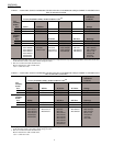
SETTINGS AND ADJUSTMENTS
L2
L1
(HOT)
1
2
M 851
W
B
R
Q209/S963 135-OHM
POTENTIOMETER
R
BW
LEFT/OUTER
AUXILIARY
SWITCH
RIGHT/INNER
AUXILIARY
SWITCH
OUTER AUXILIARY CAM
INNER AUXILIARY CAM
T1 T2
STROKE ADJUST
CAM (BROWN)
3
3
1
2
3
Power supply. Provide disconnect means and
overload protection as required.
Transformer may be external or internal.
Cam arrangement varies as shown in table.
MOTOR MODEL
M9164D1009, M9164D1007,
M9175D1014
ALL OTHER TRADELINE
MOTORS
Red
INNER CAM
OUTER CAM
Blue
Red
Blue
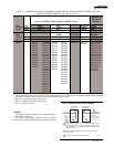
L2
L1
(HOT)
1
2
M 852
W
B
R
1
2
Q209/S963 135-OHM
POTENTIOMETER
Power supply. Provide disconnect means and
overload protection as required.
Transformer may be external or internal.
R
BW
POWER END
OF MOTOR
LEFT/OUTER
AUXILIARY
SWITCH
RIGHT/INNER
AUXILIARY
SWITCH
OUTER AUXILIARY CAM (RED)
INNER AUXILIARY CAM (BLUE)
T1 T2
STROKE ADJUST
CAMS (YELLOW)