


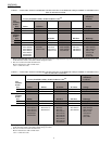
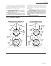

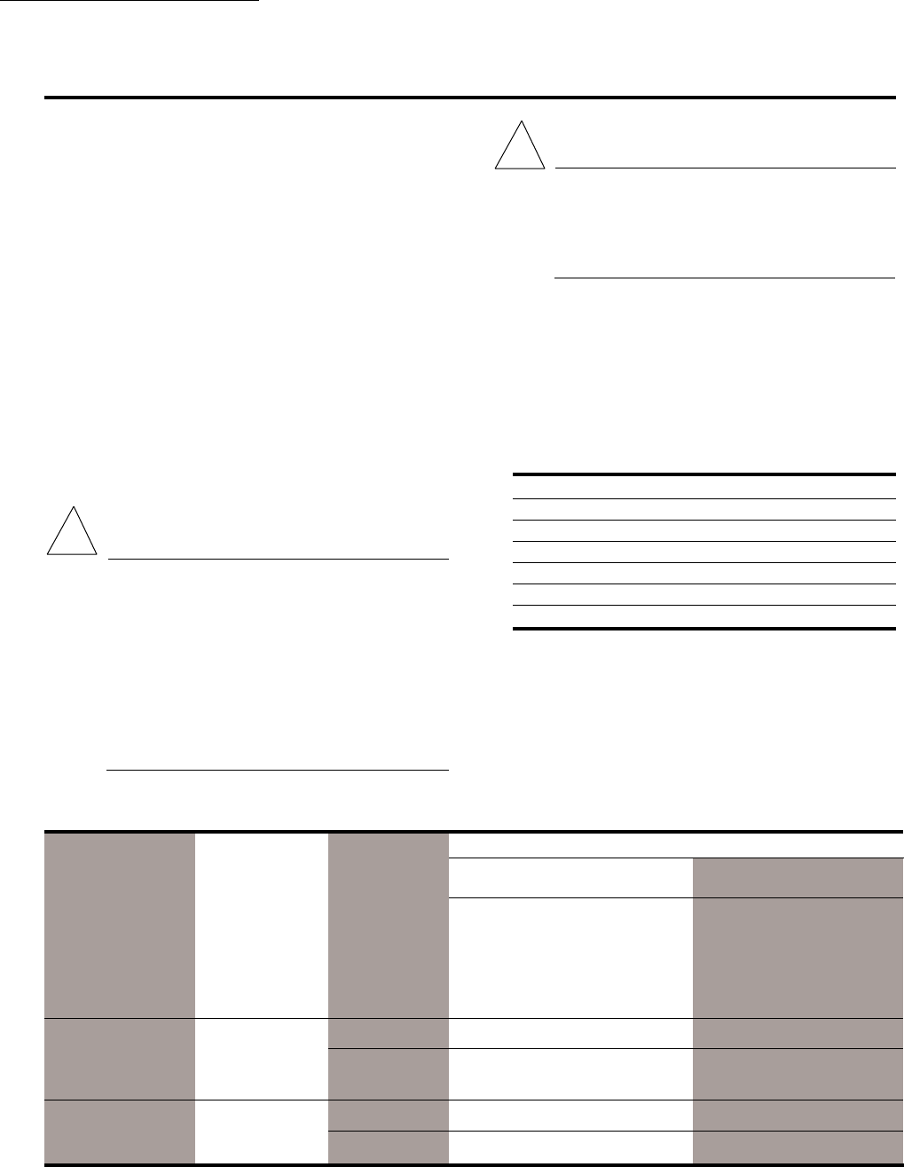
TABLE 4—AUXILIARY SWITCH POSITION WITH MOTOR SHAFT ROTATED TO EITHER SIDE OF
AUXILIARY SWITCH OPERATING POINT, AS VIEWED FROM POWER END.
Auxiliary Switch Contact Positions
N.O. Contact
a
N.C. Contact
a
(Red and Purple Leads) (Red and Orange Leads)
Shaft Shaft Shaft Shaft
Rotated Rotated Rotated Rotated
ccw of cw of ccw of cw of
Switch Switch Switch Switch
Motor Cam Switch Operating Operating Operating Operating
Type Arrangement Differential Point Point Point Point
TRADELINE, Red inner 1° Closed Open Open Closed
low and cam, blue
medium outer cam 10° Open Closed Closed Open
torque, series 91
All other Blue inner 1° Open Closed Closed Open
TRADELINE cam, red
motors outer cam 10° Closed Open Open Closed
a
cw = clockwise
ccw = counterclockwise
CAUTION
1. Live circuits are exposed during auxiliary
switch adjustment procedure. Always turn off
power before adjusting switch cams.
2. Do not turn motor shaft by hand or with
wrench as damage to the motor can result.
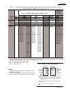
NOTE:The following instructions are for normally closed
motors (motor shaft rotates clockwise, as viewed from
the power end of the motor, on an increase in signal).
Exact adjustment procedures vary for different
TRADELINE motor models. Find your model on the
following list. Then proceed to the correct section for that
model.
Motor Model Section
M8185 A
M9164, M9174, M9175 B
M9184, M9185, M9194 C
M6284, M6294 D
M6285 E
M6184, M6194 F
Additional instructions may also be found in the Aux-
iliary Switch Adjustment section in the specification sheet
included with the Modutrol IV Motor.
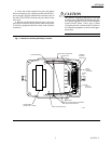
Review Table 4 and Fig. 3 before adjusting cams. Table
4 applies to both the left and right switches.
6
220736A,B
SETTINGS AND ADJUSTMENTS
Setting and Adjustments
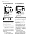
AUXILIARY SWITCHES
The auxiliary switches are spdt switches that are actu-
ated by adjustable cams. The cams are factory mounted on
the motor shaft at the power end of the motor. The settings
of the cams determine the point in motor shaft rotation at
which the auxiliary equipment will be switched on or off.
These cams can be set to actuate the switches at any angle
within the stroke of the motor. All TRADELINE motors
include auxiliary switch cams which permit installation of
this auxiliary switch kit (220736A, 220736B).
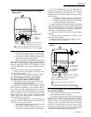
NOTE: When the slow-rise portion of the cam is used, the
switching differential is approximately 10° of rotation.
When the fast-rise portion of the cam is used, the switch
differential is approximately 1° of rotation. Do not use
the fast rise portion of the cam if fast cycling of
auxiliary equipment is undesirable.
AUXILIARY SWITCH ADJUSTMENT
PROCEDURE
WARNING
FIRE OR EXPLOSION HAZARD
CAN CAUSE SEVERE INJURY OR DEATH
When auxiliary switches control combustion
equipment, incorrect wiring of the switches can
allow the burner to come on at high fire. Check
auxiliary switch wiring and cam adjustment be-
fore turning on the system. Watch the controlled
equipment through one complete cycle. Shut the
system down immediately if switches do not
correctly sequence the equipment .
!
!