


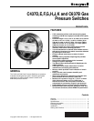

C437D,E,F,G,H,J,K AND C637B GAS PRESSURE SWITCHES
60-2320—9
5
CAUTION
Disconnect all power to the pressure switch before
beginning installation to prevent electrical shock and
equipment damage.
IMPORTANT
1. Remove the dust-seal label from the vent tapping
before mounting.
2. Accurately level the pressure switch for proper
operation.
3. The C637B pressure switch is a low differential
device. Mount it in a vibration-free location to prevent
chattering.
4. Do not hand tighten the pressure switch by holding
the case.
Follow local codes or ordinances
in all cases
when different
from these recommendations.
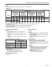
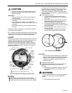
Fig. 1 shows the mounting dimensions for the C437 and C637
models, and for the accessory mounting bracket (standard on
C437G and H). See Fig. 2 for the individual components.
Location
Mount the gas pressure switch downstream from the pressure
regulator. Mount low gas pressure switches upstream of any
shutoff valve. Mount high gas pressure switches just
upstream from the burner. When pipe mounting, locate the
device on the portion of the pipe that is most level because
the mercury switch requires level orientation. See step 4 in
the Mounting section.
Use nipple and T for pipe mounting or the mounting
bracket for surface mounting. If a mounting bracket is
used, install the bracket before making piping
connections (standard on C437G and H). Mount the
bracket horizontally with the four 10-24 flathead tapping
screws provided.
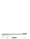
ᕤ Level the device carefully.
a. Level the device so that the point of leveling
pendulum is aligned with the mark on the inside
of the case.
b. When pipe mounting, install the device at right
angles to the pipe so that it can be leveled by
additional tightening of the pipe fittings.
c. The surface mounting bracket has elongated
holes that allow limited leveling after the mounting
screws are started.
d. Accurate leveling is most essential at very low
pressure settings.
e. If necessary, make arrangements to hold pipe-
mounted units steady and level with bracing.
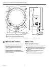
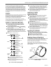
MERCURY SWITCH
PRESSURE SETTING
INDICATOR
SCALEPLATE
TERMINAL
STRIP
VENT
TAPPING
(ON SIDE
NOT SHOWN)
MAIN PRESSURE TAPPING
LENS GASKET
(G,H ONLY)
CONDUIT
TAPPING
RETAINER
SETTING
SCREW
UNDER
RETAINER
MANUAL
RESET
BUTTON
(CC437D,
E,J,K)
LEVELING
PENDULUM
REMOVE DUST-SEAL LABEL BEFORE MOUNTING
M7630
1
1
Fig. 2. Principal parts of the gas pressure switch.
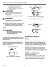
Mounting
ᕡ Remove the dust-seal label from the vent tapping.
ᕢ Remove the screws and retainers, and the cover glass.
ᕣ Mount the device on the pipe or nearby vertical surface.
M7196A
PENDULUM
LEVEL
LINE
Fig. 3. Properly leveled C437/637.
IMPORTANT
To avoid leaks and case damage, use a parallel jaw
wrench on the hexagonal part of the case close to
the pipe. Carefully make all connections and test for
leakage. Do not tighten the pressure switch by
holding the case.
ᕥ Complete the main piping.
ᕦ Connect the piping to the pressure switch. Select the
application from the following, and proceed as
instructed.
a. Hazardous-gas applications: Install a 1/8 in. NPT
pipe at the vent tapping on all hazardous-gas
applications.
WARNING
The vent must be installed so that any gas leakage is
vented into a safe place in event of a diaphragm
failure.
b. Differential-pressure applications: