


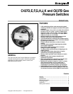
C437D,E,F,G,H,J,K AND C637B GAS PRESSURE SWITCHES
60-2320—9
6
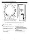
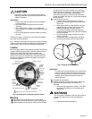
(1) Connect the high-pressure side of the
system to the 1/2 in. NPT main pressure
tapping on the gas pressure switch.
(2) Connect the low pressure side to the 1/8 in.
NPT vent tapping.
WARNING
No venting is possible in this case. Do not use this
device for differential pressure control with the
hazardous gases.
c. Negative-pressure applications: Connect the low
pressure side to the 1/8 in. NPT vent tapping.
WARNING
This application is for use only with nonhazardous
gases. Do not use this device for negative-pressure
applications with hazardous gases.
ᕧ Install other controls in the system. Connect wiring, and
complete setting and checkout before replacing the
cover glass and retainers. See Setting and Checkout
section.
Wiring
CAUTION
1. Disconnect all power to the pressure switch
before connecting wiring to prevent electrical
shock and equipment damage.
2. When using a C437F,J, or K, both ends of the
switch (W-R and B-R) must be used at the same
voltage in the same branch circuit.
All wiring must comply with local electrical codes, ordinances,
and regulations. Do not exceed the switch ratings given in the
Specifications section.
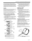
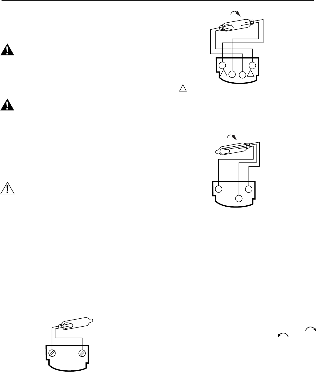
Wiring diagrams for the different models are shown in Fig. 4,
5 and 6. The switches make or break as indicated in the
diagrams. Connect the wiring to the screw terminals on the
terminal strip after removing the cover glass. Route the wires
through the conduit tapping.
TERMINAL
STRIP
M7195
C437D,G: BREAKS ON PRESSURE RISE
C437E,H: BREAKS ON PRESSURE FALL
Fig. 4. Wiring diagram for C437D,E,G,H.
1
1
1
RISE
MAKES ON
PRESSURE
FALL
MAKES ON
PRESSURE
RISE
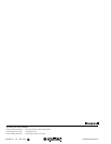
TERMINAL
STRIP
W
R
R
B
C437F,J,K
BOTH ENDS OF THE SWITCH (W-R AND B-R) MUST BE USED
AT THE SAME VOLTAGE IN THE SAME BRANCH CIRCUIT.
M7193
Fig. 5. Wiring diagram for C437F,J,K.
Fig. 6. Wiring diagram for C637B.
SETTING AND CHECKOUT
Setting
In the C437D,G and J models, the differential is
subtractive
.
The
upper
operating point is determined by the
setpoint
, while
the
lower
operating point is determined by the setpoint
minus
the differential. In the C437E,F,H,K and C637B models, the
differential is
additive
. The
lower
operating point is determined
by the
setpoint
, while the
upper
operating point is determined
by the setpoint
plus
the differential. Operating points are
shown in Fig. 7.
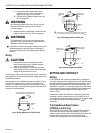
Remove the retainer and adjust the
setpoint
for the desired
operating pressure (cutout pressure on a C437D,E,G, or H
spst model) by turning the setting screw (Fig. 2) clockwise
to increase the setpoint and counterclockwise to
decrease it.
Trip-Free Manual Reset Feature
(C437D,E,J and K only)
The C437D breaks and the C437J breaks R-B and makes
R-W when the pressure rises to the setpoint. The C437E
breaks, and the C437K breaks R-W and makes R-B when the
pressure falls to the setpoint. None of these pressure
switches will automatically return to their former positions.
RISE
MAKES R TO B
ON PRESSURE
FALL
MAKES R TO W
ON PRESSURE
RISE
TERMINAL
STRIP
W
R
B
C637B
M7194