


C437D,E,F,G,H,J,K AND C637B GAS PRESSURE SWITCHES
60-2320—9
7
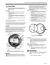
To reset one of these pressure switches, wait until the
pressure
falls
to the setpoint minus the differential (C437D or
J), or
rises
to the setpoint plus the differential (C437E or K).
Then depress the manual reset button (Fig. 2) and release it.
The pressure switch will not be reset until you release the
manual reset button
. This prevents the switch from becoming
an automatic-reset device if the reset button is stuck, held in,
or tied down.
Checkout
Adjust the setpoint for normal operation and check to see that
the gas pressure switch performs as intended. Use a
manometer or accurate pressure gauge connected upstream
from the switch to measure the actual pressure.
The most likely cause of inaccurate operation is off-level
mounting. Refer to step 4 in the Mounting section and correct
any installation that does not check out satisfactorily.
C437D,G or J (Subtractive Differential)
ᕡ Put the system into normal operation, and set the
pressure switch at the normal setpoint (above the
normal operating pressure).
ᕢ Turn the setting screw (Fig. 2) slowly toward a lower
pressure setting (counterclockwise ) to simulate a
pressure increase.
ᕣ When the setpoint is approximately equal to the
pressure indicated on the pressure gauge, the C437D
or G should break contact and turn off the controlled
equipment; the C437J should break R to B and make R
to W.
ᕤ The C437D or J should lock out.
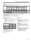
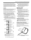
Fig. 7. C437 and C637 operating points.
ᕥ Turn the setting screw toward a high pressure setting
(clockwise ) to simulate a pressure decrease
greater than the differential
. The C437G should make
contact and turn on the controlled equipment.
ᕦ Push the manual reset button (Fig. 2) on the C437D or
J; the C437D should make, and the C437J should
break R to W and make R to B.
C437E,F,H,K or C637B
(Additive Differential)
ᕡ Put the system into normal operation and gradually
close the upstream gas shutoff valve to cause a
pressure decrease.
ᕢ When the pressure gauge indicates that the pressure is
approximately equal to the setpoint, the C437E or H
should break contact and turn off the controlled
equipment; the C437F,K or C637B should break R to W
and make R to B.
ᕣ The C437E or K should lock out.
ᕤ Open the gas shutoff valve to increase the pressure
again. When the pressure rises to the setpoint
plus the
differential
, the C437H should make contact and turn on
the controlled equipment; the C437F or C637B should
break R to B and make R to W.
ᕥ Push the manual reset button (Fig. 2) on the C437E or
K; the C437E should make, and the C437K should
break R to B and make R to W.
Completing the Installation
ᕡ Remove the pressure gauge or manometer used for
testing. Visually recheck the piping, wiring, and setting.
ᕢ Replace the cover glass and retainers.
ᕣ Return the system pressure to normal.
ᕤ Push the manual reset button (C437D,E,J or K only).
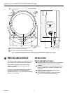
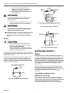
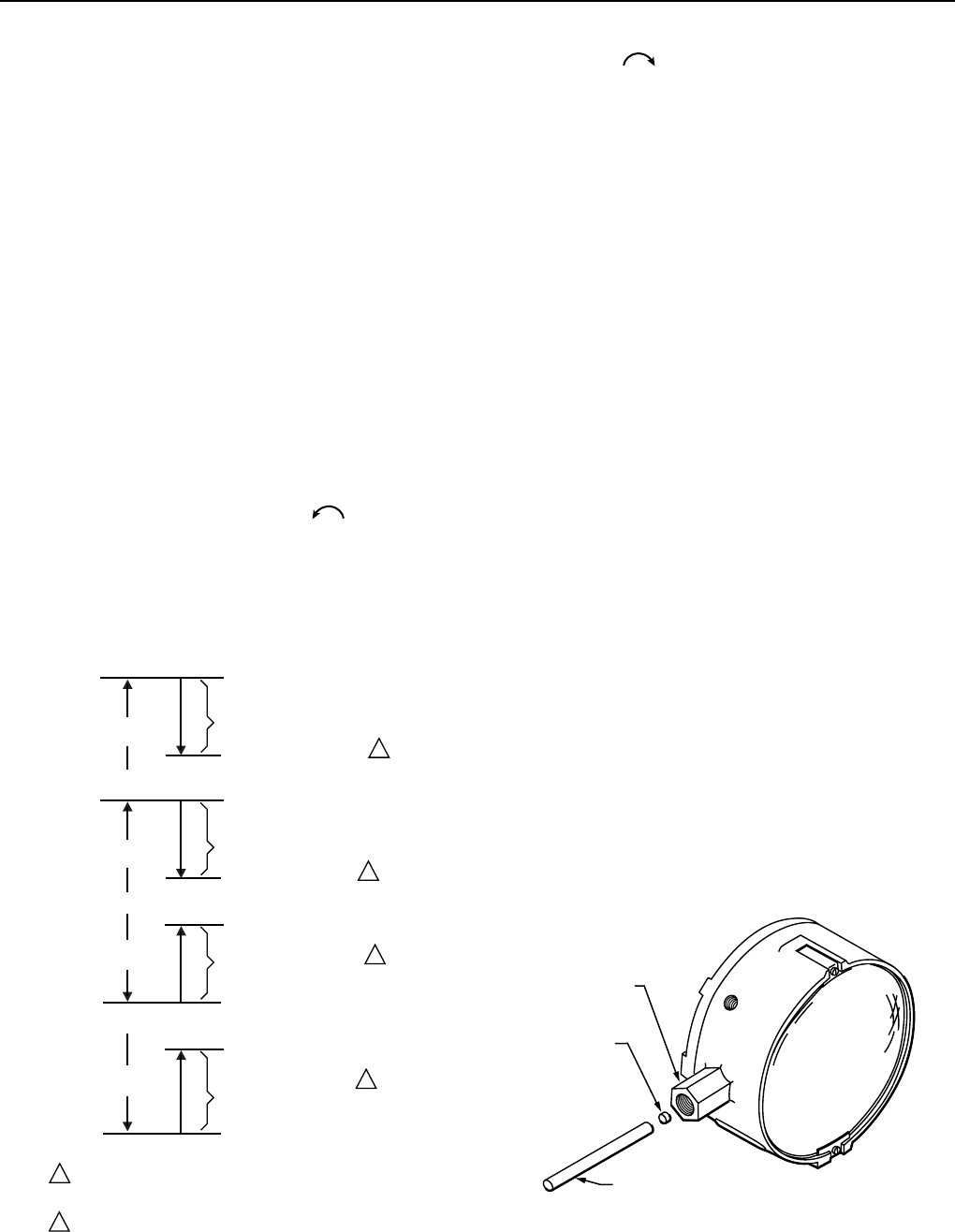
Installing a Pressure Orifice (Fig. 8)
To compensate for momentary surges in gas pressure, install
a restrictive orifice in the inlet pressure channel of the
pressure switch. (Refer to Accessories in the Specification
section for the orifice sizes available.)
Align pressure orifice into reset located inside of the main
pressure tapping at the bottom. Press orifice into place using
1/8 in. dowel rod.
PRESSURE
RISE
PRESSURE
FALL
PRESSURE
FALL
PRESSURE
RISE
SET POINT
(SWITCH BREAKS,
C437D LOCKS OUT)
SUBTRACTIVE
DIFFERENTIAL
SUBTRACTIVE
DIFFERENTIAL
SET POINT MINUS
DIFFERENTIAL (SWITCH MAKES)
SET POINT PLUS
DIFFERENTIAL (SWITCH MAKES)
SET POINT
(BREAKS R-B MAKES R-W
AND LOCKS OUT)
SET POINT MINUS
DIFFERENTIAL (BREAKS R-W,
MAKES R-B)
ADDITIVE
DIFFERENTIAL
ADDITIVE
DIFFERENTIAL
SET POINT
(SWITCH BREAKS,
C437E LOCKS OUT)
SET POINT PLUS
DIFFERENTIAL (BREAKS R-B
MAKES R-W)
SET POINT
(BREAKS R-W, MAKES R-B,
C437K LOCKS OUT)
C437D,G
C437J
C437E,H
C437F,K
C637B
C437D AND J ARE MANUAL RESET MODELS; THEY CAN BE
MANUALLY RESET WHEN THE PRESSURE FALLS TO THE SET
POINT MINUS THE DIFFERENTIAL.
C437E AND K ARE MANUAL RESET MODELS; THEY CAN BE
MANUALLY RESET WHEN THE PRESSURE RISES TO THE SET
POINT PLUS THE DIFFERENTIAL.
1
1
1
2
2
2
M7197
MAIN PRESSURE
TAPPING
PRESSURE
ORIFICE
(SELECTED)
1/8 IN. DOWEL ROD
M7191A
Fig. 8. Installing a pressure orifice to compensate for
pressure surges.