


107099-10-EN FR26 GLO 602 Printed in England 3
MECHANICAL INSTALLATION
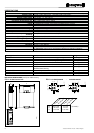
The FF-SNC Control unit must be installed inside a NEMA 3 (IEC IP 54) rated enclosure or better. The module can be
clipped easily onto a 35 mm (1.38 in.) width DIN rail (see figure 3 for installation and removal).
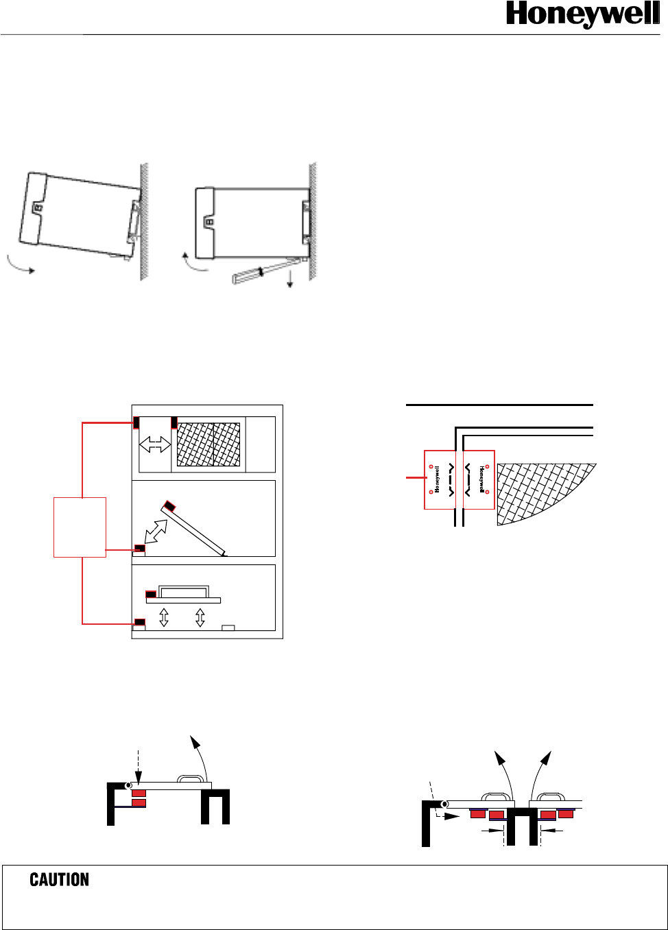
FIG 3. INSTALLATION DIAGRAM
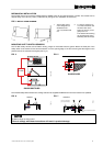
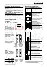
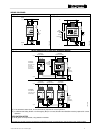
MOUNTING SAFETY SWITCH SENSORS
The FF-SNC safety swiches can be fitted to sliding, hinged or removable machine guards. Mount the fixed part of the
safety switch to the machine frame and the actuator on to the opening edge of the door ensuring that the targets on the
printed faces of the switches are aligned (see Fig. 4).
FIG. 4
SLIDING DOOR
HINGED DOOR
LIFT OFF DOOR
FF-SNC
GUARD SWITCHES
FIG. 5
FF-SNC
FF-SNC
GUARD DOOR
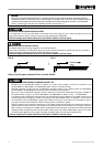
The FF-SNC safety switch sensors have 2 fixing holes and are supplied with M4x20 mm Torx Proof screws to be specified.
FIG. 6. FIG. 7
DO NOT enlarge the fixing holes!
Failure to comply with these instructions will result in product damage.
1. The FF-SNC control
unit is designed to fit
standard 35 mm /
1.37 in symmetric DIN
rail.
2. To remove: Place the tip
of a small screwdriver into
the white catch at the
bottom of the box (1) and
gently lever out.
This releases the retaining
clip and allows the unit to
be titled (2) and removed (3).
FSNC_4
Leave a 1 mm/0.039 in
gap to prevent damage
Min. 50 mm/1.97 in between actuators
as above
FSNC_3
FSNC_10EN
FSNC_5
WRONG
CORRECT