


107099-10-EN FR26 GLO 602 Printed in England 5
LID REMOVAL AND SWITCH SELECTION
ELECTRICAL SHOCK
• Remove power from FF-SNC switches and before
setup. Ensure that installation is performed by
qualified personnel.
Failure to comply with these instructions could
result in death or serious injury.
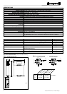
This module offers the capability to function in the
automatic start mode or manual start mode. To set the
desired mode of operation, insert the start push-
button between terminals X1/X2 for manual start
mode or insert a jumper between X1/X2 for
automatic start mode to function.
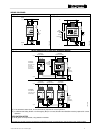
LID REMOVAL
The central part of the
FF-SNC lid (1) is
removable. Using a small
screwdriver in the recess
(2) gently prise the lid
upwards.
This allows access to the
Guard Selector Switch (See
Fig. 11 to 13) and to the
automatic and restart mode
selector switch.
FIG. 10.
21
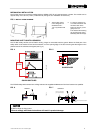
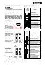
SWITCH SELECTION
Using the GATE SWITCH
SELECTOR Switch, set the
FF-SNC to the required
number of inputs.
NOTE: the number of
inputs (safety switches)
must match the gate
selector setting. Any
difference will prevent the
system from operating.
FF-SNC200R2
A1
31 13
BL
23
DR
A1
32
X2
14
BLDR
24
GATE 1
GATE 2
A1
31
X1
13
BL
23
DR
A1
32
X2
14
BLDR
24
G2
G1
G2
G1
GATE 1
GATE 2
FIG. 11.
Selector
switch
down for 1
gate
operation
FIG. 12.
Selector switch
up for 2 gate
operation
Automatic/Manual
restart:
Using the AUTOMATIC /
MANUAL SELECTOR
Switch, set the FF-SNC to
the required restart mode.
A1
31 13
BL
23
DR
A1
32
X2
14
BLDR
24
GATE 1
GATE 2
A1
31
X1
13
BL
23
DR
A1
32
X2
14
BLDR
24
A
M
A
M
GATE 1
GATE 2
FF-
SNC200
FF-
SNC400
Auto
A
(up)
A
(down)
Manual
M
(down)
M
(up)
FIG. 13.
Selector
switch up for
automatic
restart
FIG. 14.
Selector
switch down
for manual
restart
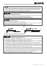
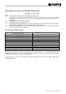
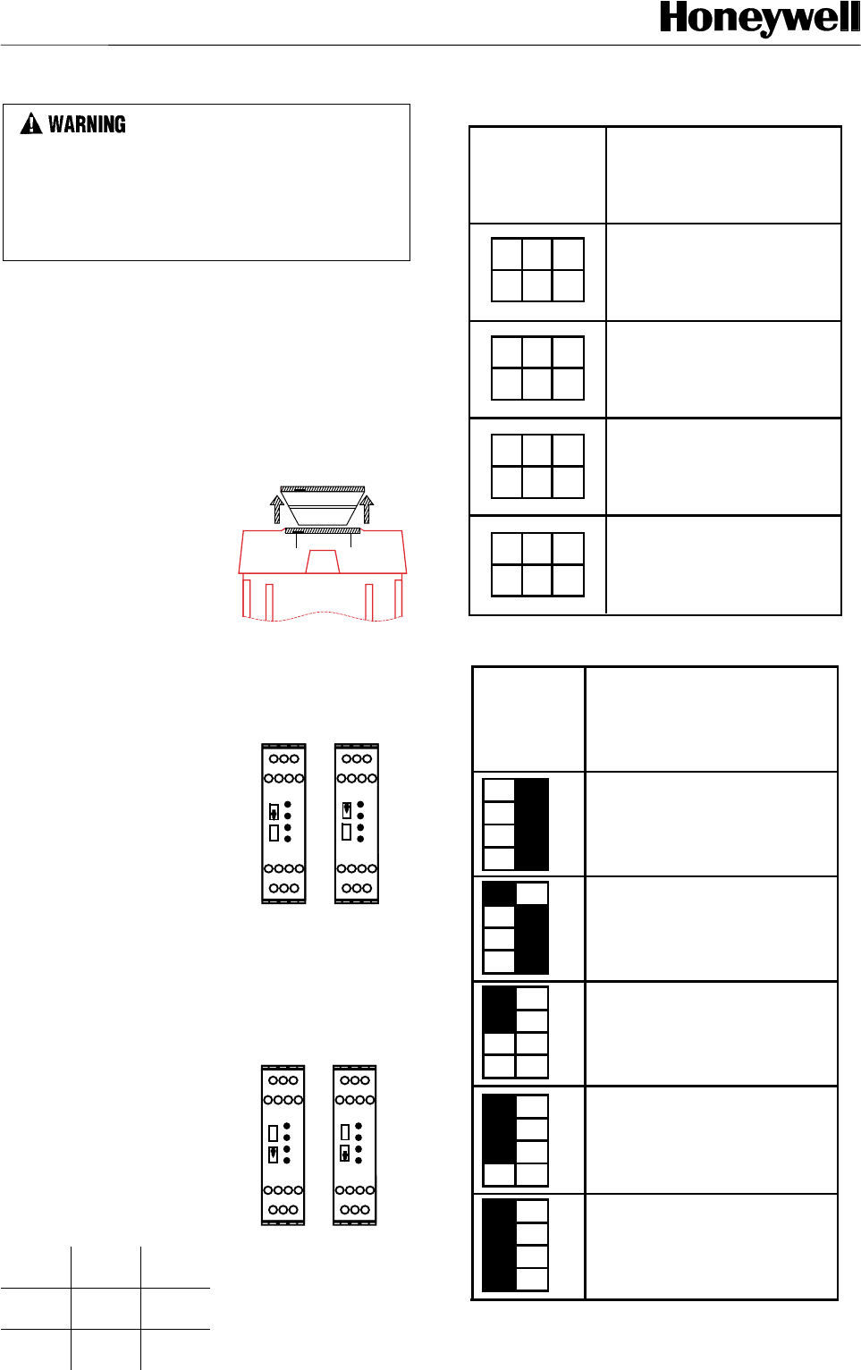
MODE SETTING LED INDICATORS
FIG. 15. FF-SNC400R❏
❏❏
❏ active gate selection
1 Gate Operation
Gate
Selector
Switch
Operation
2 Gate Operation
3 Gate Operation
4 Gate Operation
Yellow LED No.1 will illuminate when
gate switch 1 is closed
When no Green LED's are illuminated
only the first gate input is activated
Yellow LED's No.1 & No.2 will illuminate
when the corresponding gate switch is closed
The top Green LED will be illuminated
to show 2 gate inputs are activated
Yellow LED's No.1,2,3 & 4 will illuminate
when the corresponding gate switch is closed
All three Green LED's will be illuminated
to show all 4 gate inputs are activated
Yellow LED's No.1, 2 & 3 will illuminate
when the corresponding gate switch is closed
The top 2 Green LED's will be illuminated
to show 3 gate inputs are activated
234
2
3
4
23
4
234
FIG 16. FF-SNC1EXT active gate selection*
1 Gate Operation
Gate
Selector
Switch
Operation
2 Gate Operation
3 Gate Operation
4 Gate Operation
Yellow LED No.1 will illuminate when
gate switch 1 is closed
When no Green LED's are illuminated
only the first gate input is activated
Yellow LED's No.1 & No.2 will illuminate
when the corresponding gate switch is closed
The top Green LED will be illuminated
to show 2 gate inputs are activated
Yellow LED's No.1,2,3 & 4 will illuminate
when the corresponding gate switch is closed
All three Green LED's will be illuminated
to show all 4 gate inputs are activated
Yellow LED's No.1, 2 & 3 will illuminate
when the corresponding gate switch is closed
The top 2 Green LED's will be illuminated
to show 3 gate inputs are activated
G2
G3
G4
G5
5 Gate Operation
Yellow LED's No.1,2,3,4 & 5 will illuminate
when the corresponding gate switch is closed
All four Green LED's will be illuminated
to show all 5 gate inputs are activated
G2
G3
G4
G5
G2
G3
G4
G5
G2
G3
G4
G5
G2
G3
G4
G5
*If an extension module is connected, it has to be taken
into account when selecting active gates.
Active Gate Selection
FSNC_9
FSNC_24
FSNC_25
FSNC_15
FSNC_14