


4 107099-10-EN FR26 GLO 602 Printed in England
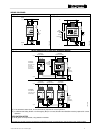
• Always try to mount the switch and actuator on non-ferrous material. Ferrous materials will reduce the switching distance.
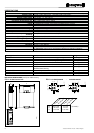
• The sensors should be mounted with a gap of approximately 1 mm/0.039 in (Fig 7). When the guard is closed, this gives a
good level of lateral tolerance to allow for “gate sag” and freedom from nuisance tripping due to machine / guard vibration.
• Leave a minimum gap of 50 mm/1.97 in between actuators as above (Fig. 7).
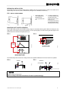
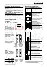
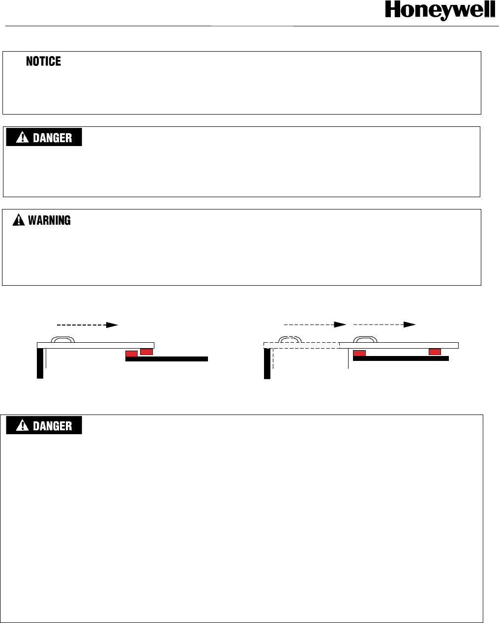
IMPROPER HINGED DOOR INSTALLATION
On a hinged door, do not mount the switch and actuator close to the hinge (Fig. 6) in order to prevent the door from
being opened while the switch is still in the scanning range specifications (State ON).
Failure to comply with these instructions will result in death or serious injury.
IMPROPER SWITCH INSTALLATION
EN 1088 provides some mounting suggestions, see examples below.
When fixing the switches to a sliding door (see Fig. 8), ensure that when the door is opened (see Fig. 9), the switch is
not easily accessible, helping prevent the system from being overridden.
Failure to comply with these instructions will result in death or serious injury.
FIG. 8. FIG. 9.
Refer to the European standards EN 811, EN 953, EN 294.
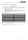
IMPROPER EXTENSION MODULE WIRING AND SET UP
• NEVER use the FF-SNC1EXT extension module as a stand alone module. It must be connected to the
FF-SNC400R2, FF-SNC400RE or FF-SNC200R2 master module, to operate correctly.
• Generally speaking, do NOT use the FF-SNC1EXT extension module if the master module (FF-SNC400R2,
FF-SNC400RE or FF-SNC200R2) can support all sensors needed in the application.
• When use of the FF-SNC1EXT extension module is required, it should be connected to the last input available on
the master module, ie "gate 4" for the FF-SNC400R2 or FF-SNC400RE or "gate 2" on the FF-SNC200R2.
• If exceptionaly the FF-SNC1EXT extension had to be used although inputs available on the master module are not
all used, make sure the extension module is connected to the next available input. For example, if only 2 sensors
are connected on the FF-SNC400R2 4-gate master module, the sensors would have to be connected to "gate 1"
and "gate 2" inputs and the extension module would have to be connected to "gate 3".
• Selector switches on the extension module and on the master module should always be positioned to reflect and
match the exact number of inputs in use, whatever is connected to these inputs (a sensor or an extension module).
• When installing or modifying an FF-SNC system, ALWAYS test correct operation by opening and closing each gate
separately. When all gates are closed and the master module reset, the master module safety outputs 13-14 & 23-
24 should be ON. When any of the gates is opened, the safety outputs 13-14 & 23-24 should go OFF.
Failure to comply with these instructions will result in death or serious injury.
FSNC_6
FSNC_7