


•HP400ULACM4CB •HP400ULACM8CB
Access Control Power Supply/Charger with Controller
PN 52898:A 4/05/06 ECN 06-221
Honeywell
12 Clintonville Road
Northford, CT 06472-1610
http://www.honeywellpower.com
Product Installation Document
This product follows under the UL1481 Fire Alarm Systems, UL603 Burglary Alarm Systems and UL294 Access Control
Systems. The HP400ULACM4 and HP400ULACM8 units are to be installed in a fail safe mode unless authorized by the
local AHJ. This product must be installed in compliance with Article 760 of the National Electrical Code, NFPA70, as
well as NAPA72 National Fire Alarm Code and all applicable local codes.
1 Description
The HP400ULACM4 and the HP400ULACM8 are 12VDC or 24VDC power supplies with HPACM4/8 access power
controllers to be used with Card Access Systems. They provide 12/24VDC through 4 or 8 independently controlled
power-limited PTC protected outputs. They accept inputs from open collector sink or Normally Open (NO) dry contacts
from UL listed security devices such as keypads, card readers, access control systems, PIR’s and Push Button Delays.
Outputs from the HPACM4 and HPACM8 can switch power on or off at 12 or 24VAC/DC. Each output can be configured
to respond to FACP input. The outputs can also be individually selected as isolated dry contacts (Form “C” configuration).
The HPACM4 and HPACM8 can be configured for common power, which means the same supply drives both output
power and control board power or alternatively, dual power input, which separates control board and output power. These
units have not been evaluated for elevator equipment and are not authorized for bell output in Mercantile applications.
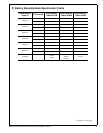
2 Specifications
A) Power Supply Board
1. Input voltage: 120VAC 60Hz; Current: 2.50A max.
2. Output Voltage: 12VDC or 24VDC, jumper selectable; Current: 4.0A continuous output maximum, 3.5A plus battery
charger (DC output not supervised).
3. Fail safe dry contact output on AC Failure (within one minute).
4. Built-in charger for sealed lead acid or gel cell type batteries.
5. Instantaneous transfer to stand-by battery on AC failure.
6. Battery presence detection (within 1 minute).
7. Battery low disconnect at 9.90VDC or 19.90VDC.
8. High voltage disconnect at 15VDC or 30VDC.
9. Yellow LED (L3) indication for battery disconnected and battery low.
10. Fail safe dry contact output for Battery trouble (Fail Safe).
11. Battery polarity reversal protection.
12. Thermal overload and short circuit protection.
13. DC output PTC activated indication by Red LED (L2).
14. DC output failure indication by Red LED ( L4 ).
15. AC presence indication by Green LED ( L1 ).
16. DC output indication by Red LED ( L5 ).
17. Battery Leads included.
18. Power Board Dimensions: 6.2”L x 4.7”W x 2.5”H.
19. Enclosure Dimension: 17”L x 13.5”W x 4.75”H. Accommodates two 12 Volt 12AH batteries. When using
larger batteries, a UL approved enclosure must be used.
B) Access Power Controller Board
1. Input
Continued on next page...