


2 HP400ULACM4/8CB Installation Document P/N 52898:A 4/05/06
• Power supply input 12 or 24 VAC/VDC.
• Common Power supply as shipped or dual power supply by cutting links JJ1 and JJ2
• Max. Controller power consumption;
– HPACM4 200mA at 12VDC, 187mA at 24VDC.
– HPACM8 379MA at 12VDC, 288mA at 24VDC
2. Outputs
• 4 or 8 independent Fail Safe or Fail Secure Normally Open (NO) or open collector sink (not supervised).
• Individually selected outputs for isolated dry contacts by removing J1 through J4,(J8)
• Individually selected outputs programmable by dip switch to follow FACP input.
• Each PTC protected output rated 2.5A @ 23C with a maximum of 2.0A @ 49C
• Automatic Yellow LED status indication of activated PTC.
• Test push button lights Yellow LED’s to verify their operation.
• Red LED individual indication for each energized relay output
3. Fire Alarm Control Panel Input
• Polarity reversing input
(REV/POL).
• Normally open (NO) or normally closed (NC) supervised input with 2.2K Ohm (EOL) resistor.
• Engineering Reset (Optional) normally open (NO) or normally closed (NC) input with 2.2 K Ohm (EOL) resistor.
4. Alarm Outputs
• Alarm outputs are Fail Safe (not supervised).
• When FACP activation occurs dry contacts activated.
• Green LED indication when FACP is activated.
• Dry contacts output for power failure to the HPACM4 and HPACM8.
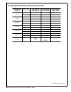
5. Board Dimensions
• HPACM4 -- 5.9” L x 4.5” W x 1.25” H (15 cm L x 11.43 cm W x 3.175 cm H).
• HPACM8 -- 8” L x 4.5” W x x1.25” H (20.32 cm L x 11.43 cm x 3.175 cm H)
3 Installation Instructions
1. Mounting
The power supply should be installed in accordance with all Governing National Electrical and Local Codes. Mount the
power supply securely in the desired location using the four (4) mounting holes.
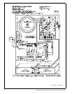
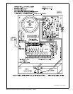
2. Power Supply Input Connection
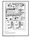
Before connecting power review the entire wiring diagram for correct installation (see Fig. 1). With the AC power
disconnected, connect 120VAC to the Fuse Block as follows; L=Black (HOT), N=WHITE (Neutral), G=GREEN
(Ground). Select the output voltage 12VDC or 24VDC using Jumper J1 of the Power Board J1 OFF=12VDC, J1
ON=24VDC. Voltage is Factory set and Re-Adjusting will void Warranty.
The HPACM4/8 controller board can be powered with one common supply (as factory wired) which will enable it to drive
the controller board and output devices, or with two (2) individual power supplies, one for the controller and one for the
devices. See Fig. 1
a) Single Power Supply (Factory Wired) - Connect the power supply (+) positive to “CONTROL” terminal (+) and
power supply (-) negative to the “CONTROL” terminal (-). T
b) Dual Power Supply - For the controller board power supply, connect the power supply (+) positive to
“CONTROL” terminal (+) and power supply (-) negative to the “CONTROL” terminal (-). For the second power
supply, connect the power supply (+) to the “POWER” terminal (+) and the power supply (-) negative to the
“POWER” terminal (-). Cut links JJ1 and JJ2.
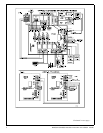
3. Input Trigger Connections
Continued on next page...