


4 HP400ULACM4/8CB Installation Document P/N 52898:A 4/05/06
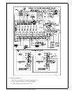
When all wiring is complete and checked, switch ON the AC Power. The Green Led (L1) will come ON indicating AC
presence and the AC relay will be energized. Connect Battery observing the correct polarity. For 24VDC use the battery
link provided to connect the two (2) 12 Volt Batteries in series. Secure the enclosure with the 4 screws and with the Key
Lock provided.
NOTE: For UL603 or UL294 applications use a Tamper Switch (Catalog number HPVM3 available separately), and
included enclosure key lock. Connect the tamper switch NC outputs to monitoring device to notify of enclosure tampering.
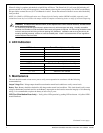
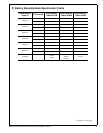
4 LED Indication
5 Maintenance
This unit should be tested at least once a year to verify correct operation in accordance with the following
recommendations;
Output Voltage Test - Voltage output should be tested under normal load conditions to verify correct levels.
Battery Test - Battery should be checked for full charge under normal load conditions. This check should verify correct
voltage at both battery terminals and also at the Battery output point on the board to ensure the integrity of all connecting
wiring. It is recommended to replace the battery at least every 4 years.
LED Test (Distribution Board only) – Verify yellow LED operation by pushing LED test button. All yellow LED’s
should illuminate.
!
WARNING: To reduce risk of electric shock, do not expose unit to rain or excess moisture, and disconnect
power before servicing unit.
For continuous protection against hazard, replace fuses only with exact type and rating. A readily accessible
switched circuit breaker must be available to disconnect main power as required. All 120V wiring should be routed
so that it cannot touch 24V wiring; minimum spacing 3/8” (0.953mm). Installation and servicing should only be
made by qualified personnel; contains no user-serviceable parts. Install in accordance with all local regulations
and the National Electrical Code.
LED Number Power Board (status when lit)
L1 Green LED - AC present
L2 Red LED - PTC activated
L3 Battery low or disconnected
L4 Red LED - DC power failure
L5 Red LED - DC output present
LED Number Distribution Board (staus when lit)
L1 - L4 Red LED - Relay enerized
L10 Green LED - FACP alarm activated
L11 - L14 Yellow LED - PTC activated
Continued on next page...