


HP400ULACM4/8CB Installation Document P/N 52898:A 4/05/06 3
a) For Open Collector activations connect the open collector to the “IN” terminal and negative to the “GND”
terminal.
b) For dry contact activation connect NO to “IN” terminal and C to “GND” terminal.
4. Output Connections
There are (4 or 8) individually configurable outputs possible: Switched Normally Open (NO), Switched Normally Closed
(NC), Switched Isolated (“Form C”) dry contacts and Un-switched continuous power output:
a) Switched Normally Open (NO) / Switched Normally Closed (NC) - Connect the negative (-) lead of the device
to the “COM” terminal. Connect the positive (+) lead of the device to the “NC” terminal for Fail Safe operation or to
the “NO” terminal for Fail Secure operation.
b) Switched Isolated Form “C” dry contacts - Connect the negative (-) of the auxiliary power supply directly to the
device, connect the (+) lead of the auxiliary power supply to the “C” terminal. Connect the positive (+) of the device
to “NC” terminal for Fail Safe operation. Connect the positive (+) of the device to the “NO” terminal for Fail Secure
operation. To program this feature the relevant output jumper (J1 to J4/J8) must be removed.
c) Un-switched continuous power output - Connect the positive (+)of the device to the “C” terminal and the
negative(-) to the “COM” terminal. In this configuration, fused power output is delivered to the devices not intended
to be affected by the Controller Board.
d) FACP input programming - To have relay activation follow FACP input place the dip switch corresponding to
the desired relay to the “OFF” position. In the “ON” position, the relay will not be affected by FACP input
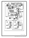
5. Fire Alarm Interface
Normally Open (NO), Normally Closed (NC) input or polarity reversal (R/POL) input from the FACP are available to
trigger the HPACM4 and HPACM8 operation. Connect the positive (+) and negative (-) from the FACP to the “R/POL”
terminals observing polarity, (polarity is referenced in alarm condition) or connect the NO or NC from the FACP output to
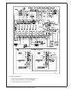
the “FIRE INTRFC” terminals. Install the 2.2K Ohm (EOL) resistor provided at the FACP as shown in Fig 1 to supervise
this connection.
6. Engineering Reset Input
This option is available when the jumper JL is removed. This will cause the HPACM4 and HPACM8 to latch upon
receiving an alarm condition from the FACP. With this option in place and when the FACP resets, the unit will only reset
by activating the “RESET” circuit.
a) JL ON
will cause the unit to follow the status of the FACP. Connect 2.2K Ohm resistor to the “RESET” terminals.
b) JL OFF
will cause the unit to latch ON until manually reset. Install the 2.2K Ohm (EOL) resistor provided at a
Key Switch or Push Button to perform this manual reset operation and to supervise this connection as shown in Fig 1.
7. Alarm/Trouble Output
a) TRBL
: When DC Power fails or PTC activates this will cause the dry contact “Form C” relay to de-energize.
b) FACP
: When the FACP activates this will cause the dry contact “Form C” relay to de-energize.
8. Cascade Connection
Two (2) or more HPACM4 or HPACM8 units can be connected together as follows; Connect the FACP relay C and NC
terminals from the 1st unit to the “FIRE INPUT” of the 2nd unit (not polarity sensitive) and remove jumper JR of the 1st
unit. If a 3rd HPACM4 or HPACM8 is used, JR must be removed from 2nd unit and so on for each new addition. See Fig.
1a.
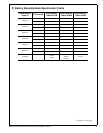
9. Power Board Connections
Connect the “AC Fail” output “Form C” dry contacts to the monitoring device. In case of AC loss the relay, which is Fail
Safe, will de-energize within one (1) minute. Connect the Battery Fail output “Form C” dry contacts to the monitoring
device. If a Battery is not connected or improperly connected, the Yellow LED (L3) will turn ON within one (1) minute
and the Battery Fail output relay, which is Fail Safe, will de-energize.
10. Power Up
Continued on next page...