


Instruction Manual
LX3000 Diesel Fire Pump Controller
Introduction
Model LX3000 engine controllers, automatically control the operation of diesel engine driven centrifugal fire
pumps.
Installation
1. Consult the Controller nameplate to verify that the DC voltage and ground polarity matches the engine
battery. Also verify that the Controller AC power requirement matches available AC power.
2. Set the CONTROLLER ON / OFF - RESET SWITCH (inside controller) to the OFF position.
C
AUTION: Before drilling and punching holes in the cabinet for wiring connections, cover the
components inside the cabinet with a protective covering. Debris may cause shorts or
prevent operation of components.
3. 2 holes are pre-punched in the top left side of the cabinet for conduit entry.
4. Connect the water line to the INLET side of the solenoid valve located on the left side of the Controller.
Connect a drain line to the DRAIN side of the valve.
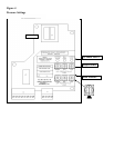
5. Connect Engine and Battery leads to TB1-1 through 12, connect the AC input to TB2-1 through 5, and
connect required alarm contacts, all per the Field Connection drawing supplied with the controller.
6. Connect remote start normally closed input contacts (if used) to TB1-13 and battery common.
7. Connect lockout/low suction normally open input contacts (if allowed by local jurisdiction) to TB1-14 and
battery common.
Start Up Instructions
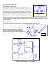
1. Adjust the pressure switch set points to meet water system requirements. The adjustment switches are
located on the pressure switch control board, which is contained inside the pressure recorder enclosure.
Open the pressure recorder door and loosen the two chart plate screws. Swing the chart plate outwards to
gain access to the pressure switch control board. Set the STOP (HIGH) pressure setting on the upper three
switches. Set the START (LOW) pressure setting on the lower three switches.
The Green LED on the left (Excitation Voltage) indicates that the Gauge Transducer is connected and
power is available to the recorder. The middle LED (Relay Status) is bi-colored to indicate the status of the
output relay contacts. If this LED is green, pressure is above the Stop pressure. If the LED is red, pressure
is below the Start pressure. The red LED to the right (CAUTION) indicates the Start pressure is set higher
than the Stop pressure and needs to be corrected.
2. Set the recorder time using a coin or screwdriver to turn the chart hub clockwise to the time indicator on
the right side of the chart.
3. Remove the pen tip cover. If necessary, adjust the pen with the adjusting screw in the upper left corner of
the dial plate. The recorder accuracy is 2% of scale.
4. Adjust the weekly Test Timer for the correct timing settings as follows:
Set the time
1) Press the Reset button to clear the memory