


General Specifications for
LXi
Controllers
These fire pump controllers are factory assembled, wired, and tested as a unit assembly, and conform to the
requirements of the latest editions of NFPA-20 and NFPA-70, and are Listed/Approved by and bear the label of
Underwriters’ Laboratories and Factory Mutual. The controllers are equipped with Hubbell’s
LXi
microprocessor
logic.
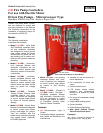
The controllers are of the combined manual/automatic type and furnished in a floor mounted drip-proof steel
Type 2 enclosure with lifting eyes. The enclosures are red with a non-glare surface. The controllers are
designed, tested, and marked for the rated horsepower and 3-phase voltage and frequency in a 40 degree C.
ambient.
All electrical components are accessible from the front for maintenance and service. No components or
component wiring are on the door of the enclosure. The controllers have a common operating handle for both
the line isolating switch and the controller circuit breaker mounted in the enclosure flange. The minimum
withstand rating for the fire pump controller is 100,000 amps RMS symmetrical at 200-480 volts. The
controllers are Listed/Approved with UL/FM as “Suitable For Use As Service Equipment”.
The controllers have separate and independent pressure settings with minimum run timing capable of a setting
up to 10 minutes. Settings of the pressures should be established at the time of the field acceptance test.
Provisions are included to allow manual or automatic shutdown in the field.
Provided are two sets of Form “C” contacts for Pump Running, Phase Reversal, and Power/Phase Failure, and
one set of Form “C” contacts for Trouble. The Trouble contacts are activated by the following: Invalid
Configuration Memory, Emergency Manual Start, Pump Running, Phase Failure, Phase Reversal, Overload,
Locked Rotor, Fail-to-Start, and Lockout.
These controllers are equipped with
LXi
intelligent fire pump control system logic.
All firmware is non-volatile
flash based CPLD (
complex-programmable logic device).
The boot-up time for the logic is 3 seconds or less.
An RS232 serial port shall be supplied for downloading event history to a PC for analysis and printing.
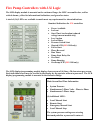
The digital pressure readings and settings are displayed on the
LXi LCD
mounted on the enclosure flange. The
LCD screen is 4 x 20 (4 lines of 20 characters) per screen, and the screens may be scrolled to give a total of
320 characters. The real time display gives simultaneous 3-phase digital amps and volts for the pump power,
and digital display for the system pressure, reducing the need for scrolling during startup.
The event alarm caches are compartmentalized, and none of the compartments over-ride other compartments.
The compartments allow for analysis of four types of information events without having to look through all
events including those not related to a problem. Events are shown with Date and Time for each event
occurrence:
1. Events that have occurred during a pump idle period
2. Events that occurred during the last start period
3. Events that occurred during the last run period
4. Events that occurred during the last stop period.
The LED display is mounted on the enclosure flange and includes LED as shown on page 2 of this brochure.
Programming of the
LXi
logic accomplished from the touch pad mounted on the enclosure flange.
Programming is password protected so that only authorized personnel can change the logic functions.