


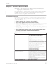

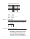
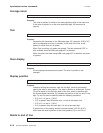
Table A-1. User character definition: Logic Controls Emulation
Mode
Byte #
Bit
0 1 2 3 4 5 6 7
1 P8 P7 P6 P5 P4 P3 P2 P1
2 P16 P15 P14 P13 P12 P11 P10 P9
3 P24 P23 P22 P21 P20 P19 P18 P17
4 P32 P31 P30 P29 P28 P27 P26 P25
5 - - - - - P35 P34 P33
* These character definitions are maintained for application compatibility
with displays with 5x8 character boxes.
←– –– –5 pixels wide – – – –→
P1 P2 P3 P4 P5 ↑
P6 P7 P8 P9 P10 |
P11 P12 P13 P14 P15 |
P16 P17 P18 P19 P20 7 pixels high
P21 P22 P23 P24 P25 |
P26 P27 P28 P29 P30 |
P31 P32 P33 P34 P35 ↓
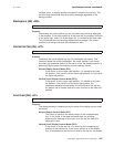
IBM Mode
IBM Mode allows nine user defined characters to be defined. See
Table A-2 for defined characters:
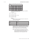
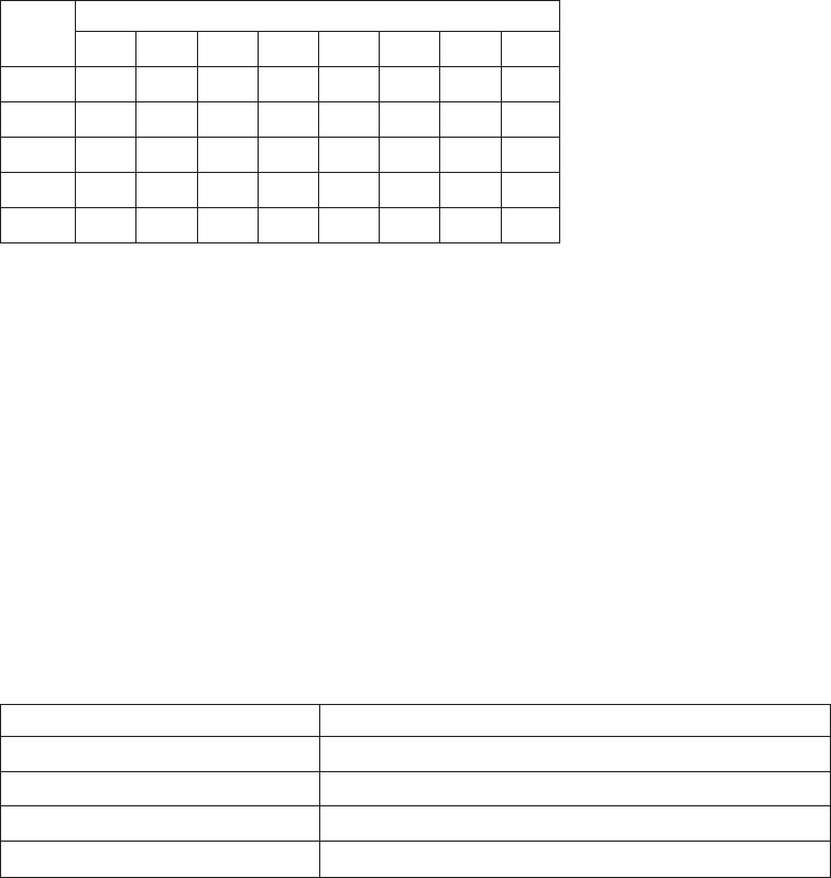
Table A-2. User character definition: IBM Mode
1. X'15' 6. X'1A'
2. X'16' 7. X'1C'
3. X'17' 8. X'1D'
4. X'18' 9. X'1E'
5. X'19'
The byte that follows the command byte represents an address
betweenX'15' and X'1A', or between X'1C' and X'1E' in the currently
selected character set. This byte is followed by eight bytes, which
define the actual bit patterns of the user-defined character.
Table A-3 on page A-4 shows the format of these eight bytes.
Note:
A hyphen character in the table indicates a do-not-care bit.
The other values relate to the character pixel positions
shown in the diagram following the table. A value of 1 in the
appropriate place in the data stream indicates that the
related pixel position is ON; a 0 indicates that it is OFF.
Input/output device commands
11-9-2005
Appendix A. Input/output device commands A-3