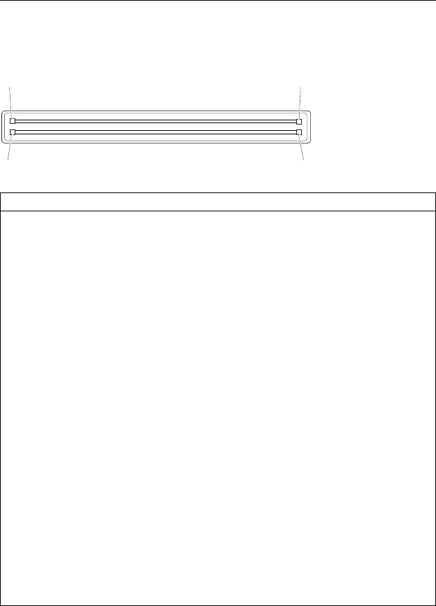
Hard Disk Drive Connector
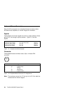
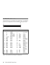
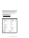
The hard disk drive is connected to the system board. The following
shows the pin assignments for the connector on the system board.
1
2
49
50
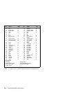
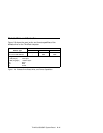
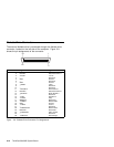
Figure 2-6. Hard Disk Drive Connector Pin Assignments
Pin Signal Description Pin Signal Description
1 JP1 Jumper
(master)
26 – Not connected
2 JP1 Jumper
(master)
27 – Not connected
3 JP2 Jumper (slave) 28 GND Ground
4 JP2 Jumper (slave) 29 −HIOW I/O write
5 – Not connected 30 GND Ground
6 – Not connected 31 −HIOR I/O read
7 −HRESET Reset 32 GND Ground
8 GND Ground 33 IORDY I/O ready
9 HD07 Data 7 34 – Not connected
10 HD08 Data 8 35 – Not connected
11 HD06 Data 6 36 GND Ground
12 HD09 Data 9 37 HIRQ Interrupt
Request
13 HD05 Data 5 38 – Not connected
14 HD10 Data 10 39 HA01 Address 1
15 HD04 Data 4 40 – Not connected
16 HD11 Data 11 41 HA00 Address 0
17 HD03 Data 3 42 HA02 Address 2
18 HD12 Data 12 43 −HCS0 Chip select 0
19 HD02 Data 2 44 −HCS1 Chip select 1
20 HD13 Data 13 45 −DASP Drive
(active/slave
drive present)
21 HD01 Data 1 46 GND Ground
22 HD14 Data 14 47 +5V +5V dc
23 HD00 Data 0 48 +5V +5V dc
24 HD15 Data 15 49 GND Ground
25 GND Ground 50 – Not connected
2-8 ThinkPad 560/560E System Board


