


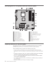
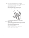
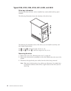
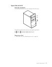
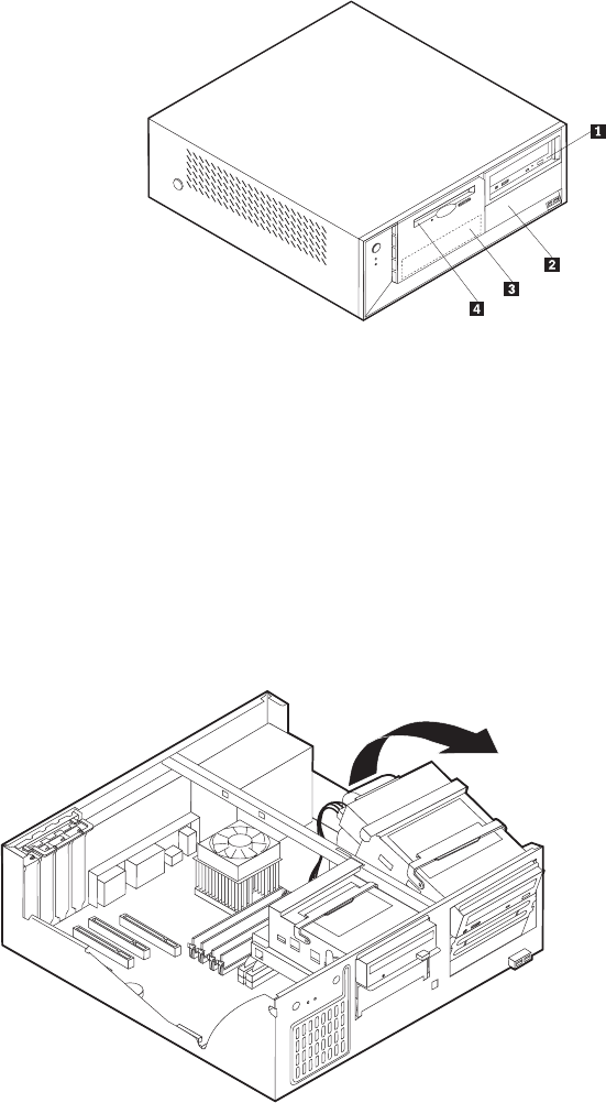
The following illustration shows the locations of the drive bays.
The following list describes some of the drives that you can install in each bay and
their height requirements:
Bay 1 and Bay 2- Maximum height: 43.0 mm (1.7 in.)
Bay 3 and Bay 4- Maximum height: 25.8 mm (1.0 in.)
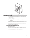
Removing a drive
1. Remove the cover. See “Removing the cover” on page 30.
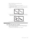
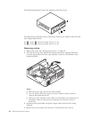
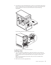
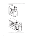
2. Pivot the drive-bay latch handle toward the front of the computer and then
pivot the appropriate drive-bay cage upward, as shown, until latched in the
upright position.
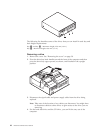
Notes:
a. Both drive-bay cages pivot in the same manner.
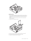
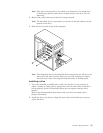
b. You can lift the drive-bay cages out of the chassis to make it easier to
remove and install the drives.
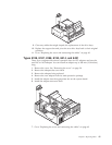
c. Take note of the location of any cables you disconnect. You might have to
disconnect cables to other drives to gain access to the drive you are
removing.
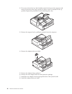
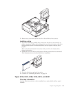
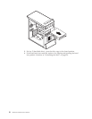
3.
Disconnect the signal cable and power supply cable from the drive being
replaced.
4. Remove any screws that secure the drive. Not all drives have screws.
46 Hardware Maintenance Manual