


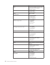
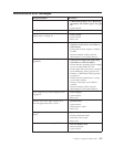
Power supply connectors
These tables enable you to check the power supply voltages.
Connector P1
OUTPUT CONNECTOR PINS WIRE COLOR TOLERANCE
+3.3 Vdc 1, 2, 11 Orange +5%, -5%
DC return 3, 5, 7, 13, 15, 16, 17 Black N/A
+5 Vdc 4, 6, 19, 20 Red +5%, -5%
Power Good 8 Gray N/A
+5 AUX 9 Purple +5%, -5%
+12 Vdc 10 Yellow +5%, -5%
-12 Vdc 12 Blue +10%, -10%
On/Off 14 Green N/A
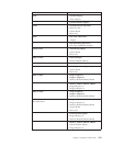
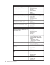
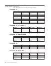
Connector P2, P3, P4, and P7
OUTPUT CONNECTOR PINS WIRE COLOR TOLERANCE
DC return 2, 3 Black N/A
+5 Vdc 4 Red +5%, -5%
+12 Vdc 1 Yellow +5%, -5%
Connector P5 (Diskette drive)
OUTPUT CONNECTOR PINS WIRE COLOR TOLERANCE
DC return 2, 3 Black N/A
+5 Vdc 1 Red +5%, -5%
+12 Vdc 4 Yellow +5%, -5%
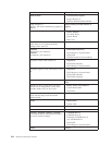
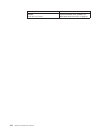
Connector P6
OUTPUT CONNECTOR PINS WIRE COLOR TOLERANCE
DC return 1, 2 Black N/A
+12 Vdc 3, 4 Yellow +5%, -5%
Connector P8 (Serial ATA)
OUTPUT CONNECTOR PINS WIRE COLOR TOLERANCE
DC return 2, 4 Black N/A
+12 Vdc 1 Red +5%, -5%
+5 Vdc 3 Yellow +5%, -5%
+3.3 Vdc 5 Orange +5%, -5%
110 Hardware Maintenance Manual