


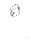
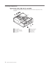
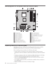
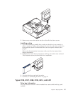
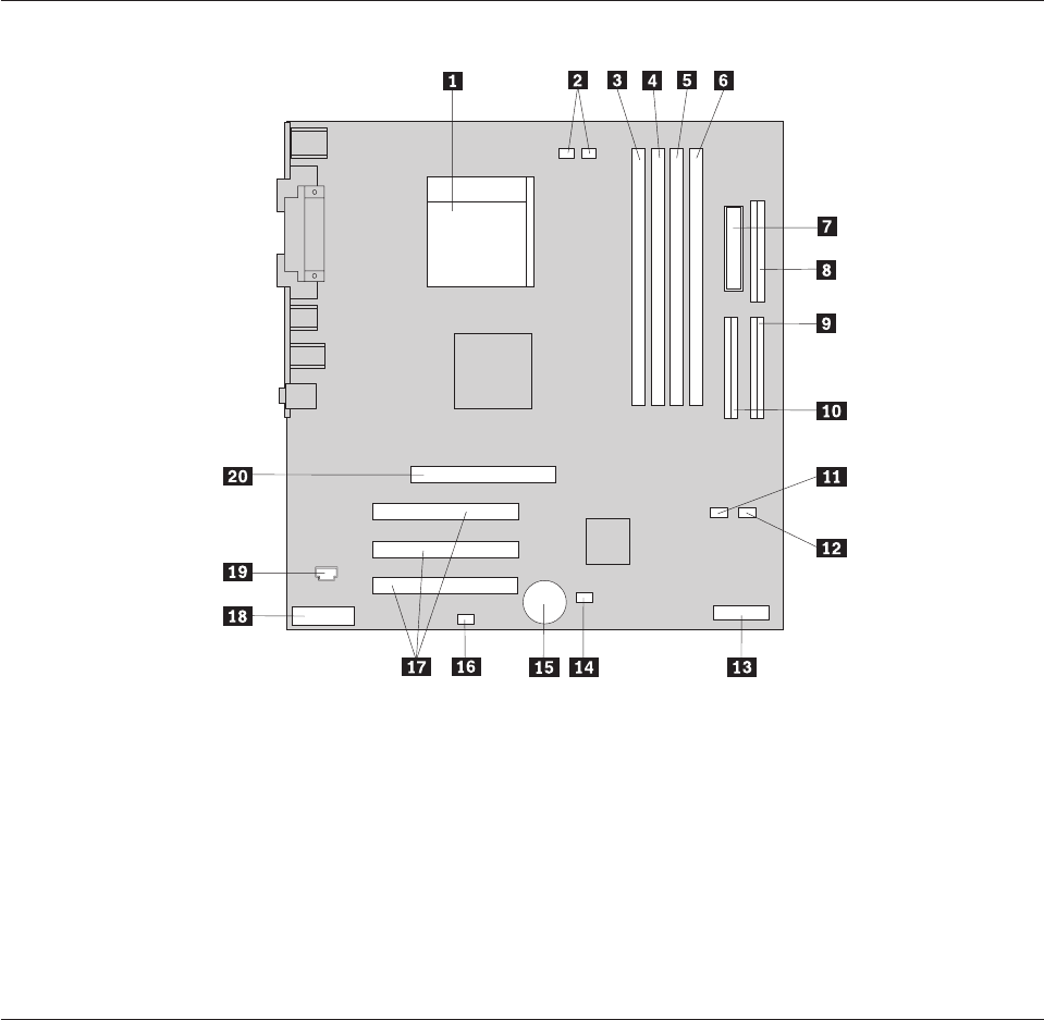
Identifying parts on the system board (all machine types)
1 Microprocessor 11SATA 1 IDE connector
2 Fan sink connectors 12SATA 2 IDE connector
3 Memory connector 1 13Security daughter card connector
4 Memory connector 2 14Clear CMOS/Recovery jumper
5 Memory connector 3 15Battery
6 Memory connector 4 16SCSI LED connector
7 Power connector 17PCI slots
8 Diskette drive connector 18Front panel audio connector
9 PATA primary IDE connector 19CD-ROM audio connector
10PATA secondary IDE connector 20AGP slot
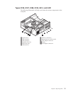
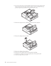
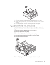
Replacing memory (all machine types)
The computer has four connectors for installing dual inline memory modules
(DIMMs) that provide up to a maximum of 4.0 GB of system memory.
When installing memory modules, the following rules apply:
v System memory is divided into two channels (channel A and B). memory
connectors 1 and 2 are channel A, and memory connectors 3 and 4 are channel
B.
v If memory connectors 1 and 3 (or 2 and 4) are filled with the same technology
and size of memory, the system operates in dual channel mode.
v Use 2.5 V, 184-pin, 333 MHz double data rate synchronous dynamic random
access memory (DDR SDRAM).
v Use 128 MB, 256 MB, 512 MB or 1.0 GB (when available) memory modules in
any combination.
v Memory modules are 25.4 mm (1.0 inches) in height.
38 Hardware Maintenance Manual