


Overview of IBM Networking
IBM Network Media Translation
BC-221
Cisco IOS Bridging and IBM Networking Configuration Guide
78-11737-02
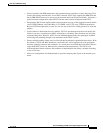
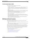
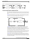
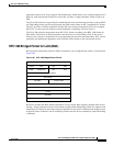
Figure 95 QLLC Conversion Running on a Router with an Intermediate IP Network
The Cisco Implementation of QLLC Conversion
SNA uses QLLC and X.25 as link layer protocols to provide a reliable connection. QLLC itself processes
QLLC control packets. In a Token Ring environment, SNA uses LLC to provide a reliable connection.
The LAN-to-X.25 (LNX) software provides a QLLC conversion function to translate between LLC and
QLLC.
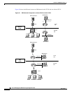
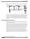
Figure 96 shows the simplest QLLC conversion topology: a single Token Ring device (for example, a
37x5 FEP) communicates with a single remote X.25 device (in this case a 3x74 cluster controller). In
this example, a router connects the Token Ring network to the X.25 network.
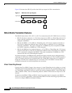
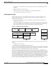
Figure 96 QLLC Conversion Between a Single 37x5 and a Single 3x74
In Figure 96, each IBM end node has no indication that its counterpart is connected to a different
medium running a different protocol. The 37x5 FEP responds as if the 3x74 cluster controller were
communicating over a Token Ring, whereas the 3x74 responds as though the 37x5 FEP were
communicating over an X.25 network. This is accomplished by configuring the router’s X.25 interface
as a virtual Token Ring, so that the X.25 virtual circuit appears to the Token Ring device (and to the
router itself) as if it were a Token Ring to which the remote X.25 device is attached.
Also in this figure, the LLC2 connection extends from the 37x5 FEP across the Token Ring network to
the router. The QLLC/X.25 session extends from the router across the X.25 network to the 3x74 cluster
controller. Only the SNA session extends across the Token Ring and X.25 networks to provide an
end-to-end connection from the 37x5 FEP to the 3x74 cluster controller.
As Figure 97 shows, a router need not directly connect the two IBM end nodes; instead, some type of
backbone WAN can connect them. Here, RSRB transports packets between Router A and Router B,
while Router B performs all conversion between the LLC2 and X.25 protocols. Only the router attached
to the serial line (Router B) needs to be configured for QLLC conversion. Both Router A and Router B
are configured for normal RSRB.
S3031
Running QLLC
X.25 network
Token
Ring
IP network
Running RSRB
Router A Router B
X.25/QLLC session TCP session LLC2 session
Router
3
7x5
Token
Ring
X.25
T0
S0
LLC2 session QLLC/X.25 session
SNA session
Virtual
ring
5
1910
32703x74