


Overview of IBM Networking
NCIA
BC-228
Cisco IOS Bridging and IBM Networking Configuration Guide
78-11737-02
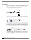
After the peer session has been established, the NDLC protocol establishes the circuit between the client
and server. This circuit is used to transfer end-user data between the client and the server. Because the
client and its target station are not on the same transport, they cannot form a direct, end-to-end circuit.
Each client must form a circuit between the client and server, and the server must form another circuit
between the server and the target station. The server links those two circuits to form an end-to-end
circuit. The server acts as a mediator between the client and the target station so that packets can be
transferred between them.
In the NCIA server only peer keepalive is maintained. There is no keepalive at circuit level.
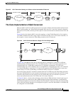
The NCIA server acts as a data-link provider, like Token Ring or Ethernet, in the router. It uses CLSI to
communicate with other software modules, just as other data-link providers do. The network
administrator configures the router to communicate with specific modules. For data-link users, such as
SNASw, DLSw+, and DSPU, the NCIA server can interface to them directly. For other data-link
providers, the NCIA server must go through a DLSw+ local peer to communicate with them. The
DLSw+ local peer passes packets back and forth among different data-link providers.
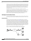
Advantages of the Client/Server Model
The client/server model used in the NCIA Server feature extends the scalability of NCIA. In addition, it
provides support for both the installed base of RSRB routers and the growing number of DLSw+ routers.
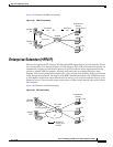
Extended Scalability
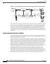
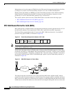
The client/server model minimizes the number of central site RSRB or DLSw+ peer connections
required to support a large network of NCIA clients (see Figure 102). Rather than each client having a
peer connection to a central site router, the clients attach to an IP backbone through an NCIA server that,
in turn, has a single peer connection to a central site router. This scheme can greatly reduce the number
of central site peer connections required. For example, in a network with 1000 clients and 10 NCIA
servers, there would be only 10 central site peer connections. Note that there would still be 1000 LLC2
connections that must be locally acknowledged at the central site router, but this can easily be handled
in a single central site router. When the number of LLC2 connections (or the number of clients) is in the
tens of thousands, NCIA servers can take advantage of downstream PU concentration to minimize the
number of LLC2 connections that must be supported by the central site routers.
Figure 102 NCIA Server Provides Extended Scalability to Support Large Networks
M
ainframe
with FEP
RSRB
RSRB
NCIA
server
NCIA
client
51914
IP
backbone
Token
Ring