


Overview of IBM Networking
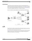
DSPU and SNA Service Point
BC-231
Cisco IOS Bridging and IBM Networking Configuration Guide
78-11737-02
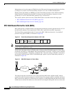
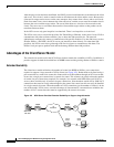
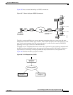
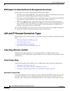
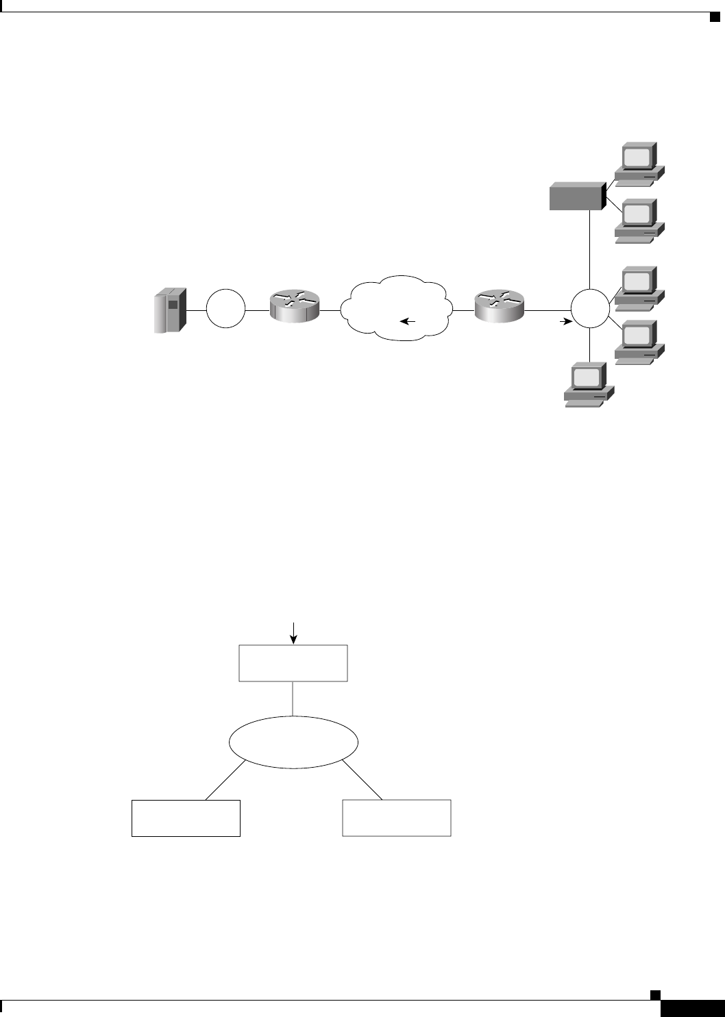
Figure 105 shows a router functioning as a DSPU concentrator.
Figure 105 Router Acting as a DSPU Concentrator
Typically, a router establishes one or more upstream connections with one or more hosts and many
downstream connections with PU type 2 devices. From an SNA perspective, the router appears as a PU
type 2 device to the upstream host and assumes the role of a system services control point (SSCP)
appearing as a PU type 5 device to its downstream PUs.
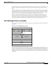
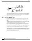
The SSCP sessions established between the router and its upstream host are completely independent of
the SSCP sessions established between the router and its downstream PUs. SNA traffic is routed at a
logical unit (LU) level using a routing algorithm that maps downstream LUs onto upstream LUs.
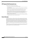
Figure 106 illustrates the SNA perspective of DSPU.
Figure 106 SNA Perspective of DSPU
Token
Ring
RSRB
Mainframe
w
ith 1 PU and
8 LUs defined
DSPU concentrator
supporting 4 PUs
and 8 LUs
LU
PU 2 + 2 LUs
S3223
Token
Ring
PU 2 + 1 L
U
PU 2 + 3 L
Us
LU
PU 2 PU 5
Upstream PU
(PU type 2)
LU routing algorithm
Downstream PU A
(PU type 5)
Downstream PU B
(PU type 5)
S3224