


2-17
Hardware Setup
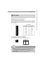
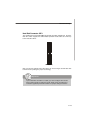
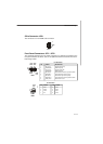
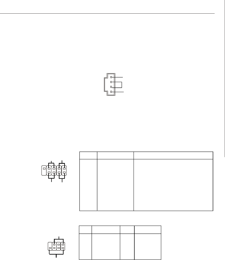
CD-In Connector: JCD1
The connector is for CD-ROM audio connector.
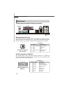
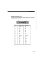
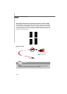
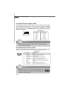
Front Panel Connectors: JFP1 / JFP2
The mainboard provides two front panel connectors for electrical connection to the
front panel switches and LEDs. JFP1 is compliant with Intel
®
Front Panel I/O Connec-
tivity Design Guide.
1
2
Power
LED
1
2
JCD1
GND
R
L
PIN SIGNAL DESCRIPTION
1 HD_LED_P Hard disk LED pull-up
2 FP PWR/SLP MSG LED pull-up
3 HD_LED_N Hard disk active LED
4 FP PWR/SLP MSG LED pull-up
5 RST_SW_N Reset Switch low reference pull-down to GND
6 PWR_SW_P Power Switch high reference pull-up
7 RST_SW_P Reset Switch high reference pull-up
8 PWR_SW_N Power Switch low reference pull-down to GND
9 RSVD_DNU Reserved. Do not use.
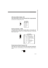
Pin Definition
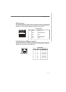
PIN SIGNAL PIN SIGNAL
1 GND 2 SPK-
3 SLED 4 BUZ+
5 PLED 6 BUZ-
7 NC 8 SPK+
Pin Definition
7
8
Power
LED
Speaker
JFP2
JFP1
9
10
Power
Switch
Reset
Switch
HDD
LED