


2-19
Hardware Setup
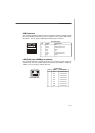
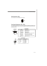
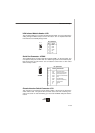
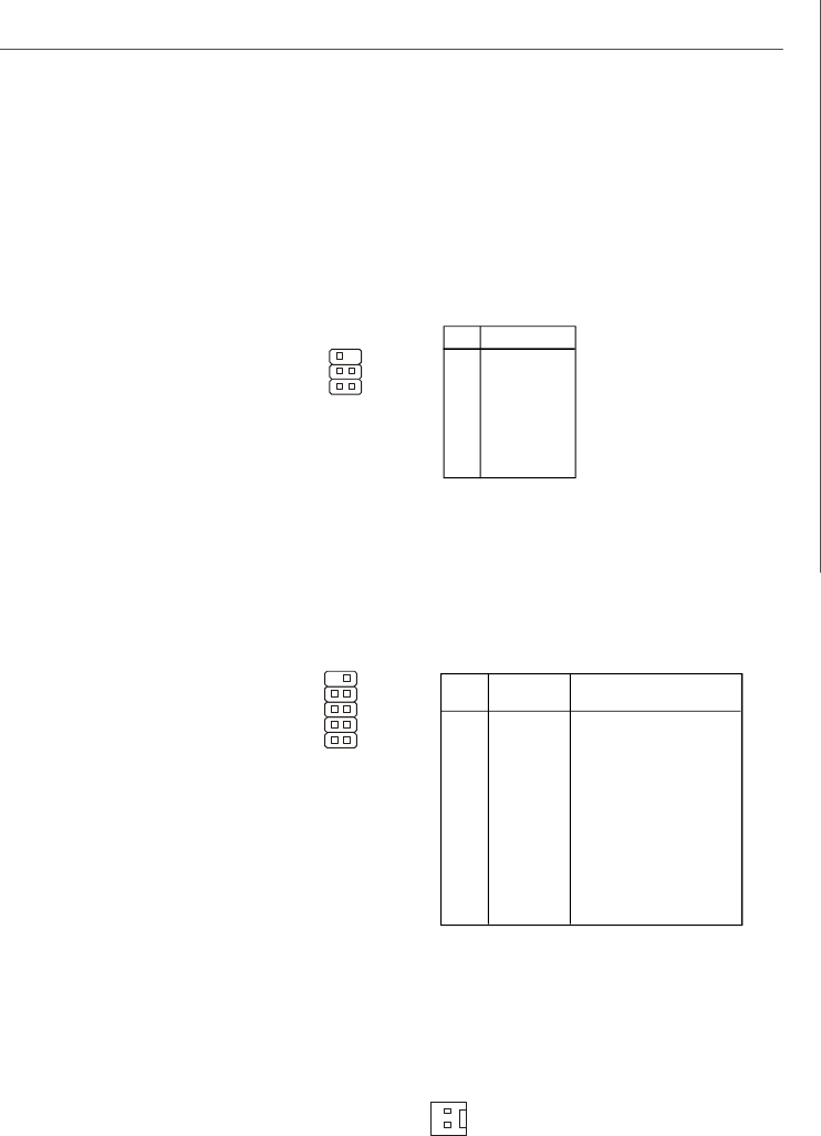
IrDA Infrared Module Header: JIR1
The connector allows you to connect to IrDA Infrared module. You must configure the
setting through the BIOS setup to use the IR function. JIR1 is compliant with Intel
®
Front Panel I/O Connectivity Design Guide.
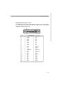
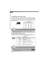
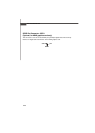
Serial Port Connector: JCOM1
The mainboard offers one 9-pin male DIN connector COM 1 (on the rear panel), and
one optional serial port JCOM1. Both are 16550A high speed communication ports
that send/receive 16 bytes FIFOs. You can attach a serial mouse or other serial
device directly to them.
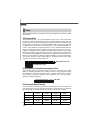
PIN SIGNAL DESCRIPTION
1 DCD Data Carry Detect
2 SIN Serial in or receive data
3 SOUT Receive Data Transmit
4 DTR Serial out or transmit data
5 GND Data
6 DSR Data Set Ready
7 RTS Request To Send Ring
8 CTS Clear To Send
9 RI Indicate
10 X X
Pin Definition
JCOM1
10 9
2 1
Pin Signal
1 IRRX
2 IRTX
3 GND
4 VCC5
5 NC
6 NC
Pin Definition
1
5
JIR1
6
2
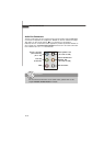
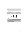
Chassis Intrusion Switch Connector: JCI1
This connector is connected to a 2-pin chassis switch. If the chassis is opened, the
switch will be short. The system will record this status and show a warning mes-
sage on the screen. To clear the warning, you must enter the BIOS utility and clear the
record.
JCI1
2
1
GND
CINTRU