


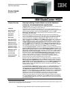
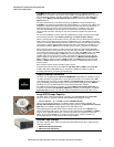

Workhorse 2-socket dual and quad-core
Intel Xeon blade server
Please see the Legal Information section for important notices and information.
9.
to backups. It also offers an extended product lifecycle (3 years in production from date of General
Availability, plus another 5 years of support).
• Backward compatibility — Every blade (but one), and every switch and passthru module released
by IBM for the original BladeCenter chassis since 2002 is supported in the BladeCenter T chassis.
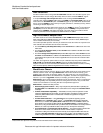
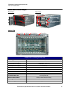
• Eight 30mm blade slots — These hot-swap slots are capable of supporting any combination of 8
Low Voltage HS20/HS21 (Xeon) blade servers, or 7 regular-voltage HS20/HS21/LS20/LS21
(Opteron), and JS20/JS21 (PowerPC 970FX/MP) blade servers, or 4 double-wide (60mm)
HS40/LS41 processor-based blade servers, or a mixture of 30mm and 60mm blades. It also
supports optional 30mm Expansion Units in combination with the blade servers, using the same
blade slots. Up to five chassis can be installed in an industry-standard 42U rack (or a telco rack), for
a total of up to 40 30mm blade servers per rack.
• Four module bays for communication and I/O switches — The modules interface with all of the
blade servers in the chassis and eliminate the need for external switches or expensive,
cumbersome cabling. All connections are done internally via the midplane. Two bays are reserved
for hot-swap/redundant Gigabit Ethernet switch modules. The other two bays support additional
Gigabit Ethernet modules, or Fibre Channel, InfiniBand and other switch modules. All modules,
when in stalled in pairs, offer load balancing and failover support. Integrated switch modules mean
that no extra rack “U space” is required.
• Two module bays for Management Modules — The management module provides advanced
systems management and KVM capabilities for not only the chassis itself, but for all of the blades
and other modules installed in the chassis. The Management Module provides capabilities similar to
the IBM Remote Supervisor Adapter II used in stand-alone xSeries rack and tower servers. The
features of the Management Module can be accessed either locally or remotely across a network.
One module comes standard. A second Management Module can be added for hot-
swap/redundancy and failover. The modules include a light path diagnostics panel containing
LEDs that identify which internal components are in need of service.
• Four module bays for Blower Modules — All four hot-swap/redundant blower modules come
standard with the chassis. These modules replace the need for each blade to contain its own fans.
The blowers are more energy efficient than dozens or hundreds of smaller fans would be, and they
offer many fewer points of potential failure.
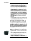
• Four module bays for Power Modules — BladeCenter T ships with two 1300W high-efficiency
hot-swap/redundant DC or AC (model-specific) power modules (upgradeable to four), capable of
handling the power needs of the entire chassis.
• Redundant Midplane connections — By giving each blade two physical connections to the
midplane that connects all blades and modules together internally, a failure of one connector alone
cannot bring down the server.
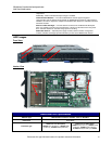
• A Tray containing a CD-ROM drive, KVM ports, two USB 1.1 ports, and a light path diagnostic
panel — The media tray is shared by all the blades in the server. This eliminates unnecessary parts
(and reduces the number of parts than can fail). A floppy drive is optional.
• Long-life availability — The BladeCenter T chassis will be produced for at least 3 years from date
of General Availability. This allows telecom Network Equipment Manufacturers (NEPs) and, Service
Providers (SPs) to standardize on a configuration for longer than traditional enterprise platforms.
Product availability for periods longer than 3 years will be handled on an individual basis.
• It is extremely important to include all infrastructure costs when comparing a BladeCenter T
solution to a competitor’s offering, not just the cost of the chassis and the blades. The high density
and level of integration of the BladeCenter T chassis can greatly reduce the cost of the overall
solution. For example, because up to five chassis will fit in a rack, this means that up to 40 blade
servers can be installed. Also, because up to four Ethernet, Fibre Channel or other supported
switches can be installed per chassis, up to 20 switches can be installed per rack without having
to reserve any “U” space for switches. (And the integrated switches may be less expensive than
external, self-powered switches.) Plus, the number of power distribution units (PDUs) needed
per rack may be lessened, because there are fewer discrete devices to have to plug in. In addition,
because all the blades are connected to all the switches inside the chassis, there is no need for
external Ethernet or other communication cables to connect the blades and switches. (Only
the few cables needed to connect the switches to the external world are required.) This not only can
save the cost of numerous cables per rack, but also the clutter and bother of routing that many
cables. An added bonus is potentially much freer airflow behind the rack, due to fewer cables.
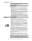
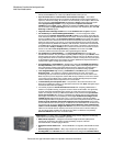
Light Path Diagnostics
Light path diagnostics enables a technician to quickly identify and locate a failed or failing
system component, such as a specific blower module or memory DIMM. This enables quick
replacement of the component, which helps increase server uptime and lower servicing costs.
The front of each blade server—and the chassis itself—has an LED indicator light to show
possible component failures. This lets the servicer identify the failing component without the
need to or remove the blade server from the chassis. The light path diagnostics panel tells the