


- 16 -
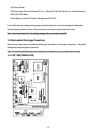
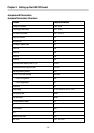
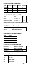
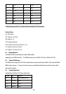
JP9 (COM1, 2) / JP4 (COM3, 4) Voltage Selector:
Voltage COM1(JP9)
COM2(JP9)
COM3(JP4)
COM4(JP4)
+12V(dc)
1-2 7-8 1-2 7-8
R.I. 3-4 9-10 3-4 9-10
+5V(dc) 5-6 11-12 5-6 11-12
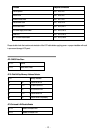
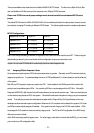
JP10, JP11: RS232 / 422 / 485 Selector for COM2
TYPE JP10 JP11
RS-232 1-2, 4-5, 7-8, 10-11 1-2
RS-422/485 Full Duplex 2-3, 5-6, 8-9, 11-12 3-4, 7-8
* Make sure the port mode is set up correctly before installing any peripherals.
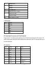
JP12’s Pin 9~11: On-board Power Good Selector
Pin 9-10 Using External Power Good
Pin 10-11 Using On Board Power Good
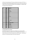
JFAN1, JFAN2: CPU / 2nd Cooling Fan Connector
Pin No. Function
Pin 1 Sensor Pin.
Pin 2 +12V
Pin 3 GND
JP12’s Pin12;13;16;17;18: For ATX Power Supply
Close Pin 16-17 Using PS/2 AT Power Supply
Close Pin 17-18 Using ATX Power Supply
Pin 12; Pin 13 On/Off Switch for ATX Power
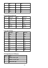
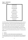
12: Case Panel Connection:
Pin No. Description
1,2 HDD_LED -/+
3,6 External Speaker
4,5 Onboard Buzzer