


Parallel Sysplex Coupling Connectivity
The Coupling Facilities communicate with z/OS images in
the Parallel Sysplex environment over specialized high-
speed links. As processor performance increases, it is
important to also use faster links so that link performance
does not become constrained. The performance, avail-
ability and distance requirements of a Parallel Sysplex
environment are the key factors that will identify the appro-
priate connectivity option for a given confi guration.
When connecting between System z10, System z9 and
z990/z890 servers the links must be confi gured to operate
in Peer Mode. This allows for higher data transfer rates
to and from the Coupling Facilities. The peer link acts
simultaneously as both a CF Sender and CF Receiver link,
reducing the number of links required. Larger and more
data buffers and improved protocols may also improve
long distance performance.
Introducing long reach Infi niBand coupling links
Now, Infi niBand can be used for Parallel Sysplex coupling
and STP communication at unrepeated distances up to 10
km (6.2 miles) and even greater distances when attached
to a qualifi ed optical networking solution. Infi niBand cou-
pling links supporting extended distance are referred to as
1x (one pair of fi ber) IB-SDR or 1x IB-DDR.
• Long reach 1x Infi niBand coupling links support single
data rate (SDR) at 2.5 gigabits per second (Gbps) when
connected to a DWDM capable of SDR
• Long reach 1x Infi niBand coupling links support double
data rate (DDR) at 5 Gbps when connected to a DWDM
capable of DDR.
Depending on the capability of the attached DWDM, the
link data rate will automatically be set to either SDR or
DDR.
The IBM System z10 introduces Infi niBand coupling link
technology designed to provide a high-speed solution and
increased distance (150 meters) compared to ICB-4 (10
meters).
Infi niBand coupling links also provide the ability to defi ne
up to 16 CHPIDs on a single PSIFB port, allowing physi-
cal coupling links to be shared by multiple sysplexes.
This also provides additional subchannels for Coupling
Facility communication, improving scalability, and reduc-
ing contention in heavily utilized system confi gurations. It
also allows for one CHPID to be directed to one CF, and
another CHPID directed to another CF on the same target
server, using the same port.
Like other coupling links, external Infi niBand coupling
links are also valid to pass time synchronization signals for
Server Time Protocol (STP). Therefore the same coupling
links can be used to exchange timekeeping informa-
tion and Coupling Facility messages in a Parallel Sysplex
environment.
51
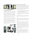
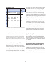
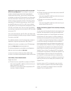
A robust failure recovery capability
ICF z/OSz/OS ICF
System z10 / z9
zSeries 990 / 890
System z10 / z9
zSeries 990 / 890
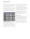
z10 EC, z10 BC, z9 EC,
z9 BC, z990, z890
ICB-4 10 meters
12x PSIFB
12x PSIFB
HCA2-O
MBA
HCA2-C
I/O Drawer
ISC-3
ISC-3
ISC-3
ISC-3
z10 EC, z10 BC
IFB-MP
z10
ISC-3
New ICB-4 cable
z10 EC, z10 BC, z9 EC,
z9 BC, z990, z890
HCA2-O LR
Up to 150 meters
Up to 150 meters
Up to 10/100
Km
.
.
.
.
.
.
.
.
.
.
.
.
.
.
.
.
HCA2-O
.
.
.
.
.
.
.
.
.
.
.
.
.
.
.
.
1x PSIFB
Up to 10/100 Km
z9 EC and z9 BC S07