


14
DC Power Wiring, Replacing Power Supply Modules and Fans
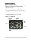
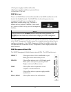
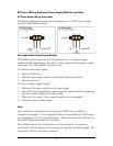
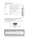
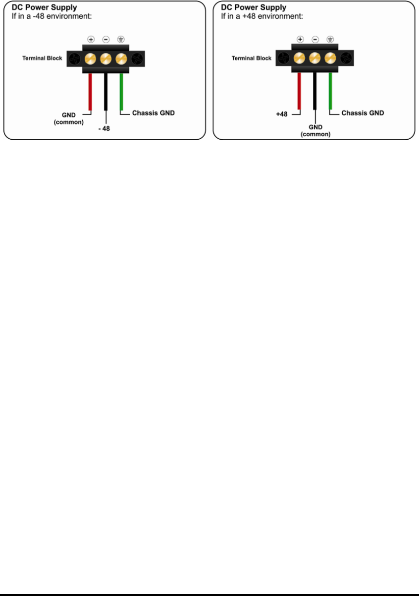
DC Power Supply Wiring Instructions
The following diagram shows the wiring configurations for -48 VDC power supply
modules for the iMediaChassis/6.
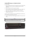
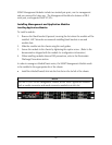
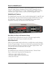
User-Replaceable Power Supply Modules
The iMediaChassis/6 ships from IMC Networks with one or two power supply
modules installed depending on the model. Chassis ordered with one power supply
come with a filler tray installed in the second slot.
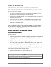
To install a second power supply:
1.
Remove the filler tray.
2.
Slide the power supply module into the chassis and click into place.
3.
Attach power cord.
To remove a power supply module:
1.
Disconnect the power source from the power supply.
2.
Move the Power Supply Release switch toward the right and hold while grasping
the power supply module by the silver handle.
3.
Slide out of the chassis. (Power supply modules are hot-swappable.)
4.
Install new power supply module.
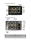
Fans
Users can define a threshold for fan operation via SNMP (when installed in a
managed environment). If a fan’s speed falls below the specified level, SNMP sends a
trap (configured in iView²) to the administrator. There are also two LED indicators on
the SNMP Management Module for fan failure.
The red Reset Alarm Switch also functions as a Fan Test button. To verify fan
functionality, hold the button down for several seconds, the fans should engage. The
fans will turn off when the button is released.