


19
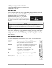
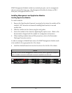
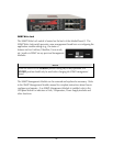
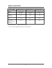
SNMP Management Module LEDs
The SNMP Management Module features several LEDs. The LED functions are:
LNK/ACT
FDX/COL
TEMP
PS
FAN A / FAN B
Glows green when a link is established on port.
Blinks green when data activity occurs.
Glows yellow when port is in Full-Duplex mode.
Blinks yellow when port is operating in Half-
Duplex mode and collisions occur.
Glows yellow when temperature of unit
surpasses a user-defined level.
Glows yellow when one power supply module
malfunctions.
Glows yellow when a fan malfunctions.
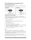
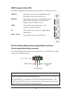
DC Power Wiring, Replacing Power Supply Modules and Fans
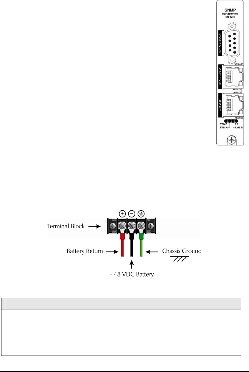
DC Power Supply Module Wiring Instructions
The following diagram shows the wiring configuration for a -48 VDC power supply
module for the iMediaChassis/3.
NOTE
Incorrect wiring will result in chassis malfunction.
The iMediaChassis/3 is compliant with Isolated Grounding Plane practices. The
POSITIVE and NEGATIVE terminals are isolated from chassis ground and must have
a ground reference at the power-sourcing equipment.