


4
INSTALLATION
Installation of the ASCO Series 165 automatic transfer
switch must be performed by a licensed electrician. It must
be installed according to the National Electrical Code and
all local electrical code requirements. Refer to the
installation d rawing a nd wiring diagram.
MALFUNCTION or SHORTENED LIFE
Protect the unit from construction grit and metal
chips to prevent malfunction or shortened life.
!
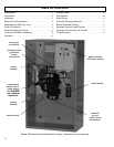
Remove the encl o sure cover and inspect the unit for ship–
ping damage. If damage is evident do no t
instal l the unit. Ty pe
1 enclosure is for i ndoo r use only ( refer to local codes fo r Ty pe
4 use). Mount the automatic transfer switch vertically to a rigid
supporting structure. L ev el all mounting points with flat
washers behind the holes to a void distortion of e nclosure.
ELECTRICAL LINE CONNECTIONS
Installation wiring must be performed by a licensed
electrician in accordance with the National Electrical Code
(NEC) and all local electrical code requirements.
The automatictransfer switch must be protected by suitably
sized circuit breakers feeding the preferred and alternate
source terminals. The ratings of the circuit breakers must be
based on t he requirements of the National Electrical Code
for its nameplate ampere and short circuit withstand ratings.
See the wiring diagram provided with the unit.
ELECTROCUTION H AZARD
Turn off utility power and turn off the
generator to prevent electrocution
when wiring the transfer switch.
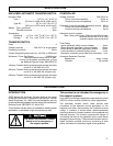
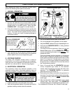
CABLE SPA CERS (200 and 230 amp. units)
Three cable spacers are included with 200 and 230 ampere
size transfer switches. Run the power cables through the
cable spacers as shown here and position the cable
spacers approximately 1½ inches from the terminal lugs.
Use copper cables for 200 and 230 amp. transfer switches.
cable spacer
cable spacers
1 ½ inch approximate
from terminal lugs
200 & 230 amp. transfer
switches require cable
spacers and copper cables
L5
L1
L3
L7
L2
L6
preferred source (utility)
alternate source (g en erator)
load
CABLE LOOSE NING DUE TO SHORT–CIRCUIT. Install
3 cable spacer s 1½ in. from termi n al lugs to pr e v e n t
cables from loosening in a short– c ircu i t con diti on .
!
CABLE CONNECTIONS (see wiring diagram)
Prepare the wires for connection as follows: strip the
insulation; avoid nicking or ringing the conductors when
stripping the cable. Remove surface oxides from
conductors by cleaning with a wire brush. Apply electrical
joint compound and wipe away excess. Insert prepared
cable into lug and tighten the lug to the torque specified on
the rating label on the transfer switch.
Connect the preferred source (utility) line 1 and 2 wires to
the t erminal lugs marked L1 and L5 at the bottom. Connect
the alternate source (generator) line 1 and 2 w ires to the
terminal lugs mark ed L2 and L6 at the upper middle.
Connect the load line 1 and 2 w ires to the terminal lugs
marked L3 and L7 at the top of the transfer switch. Neutral
and ground terminals are provided.
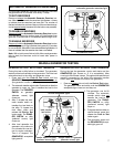
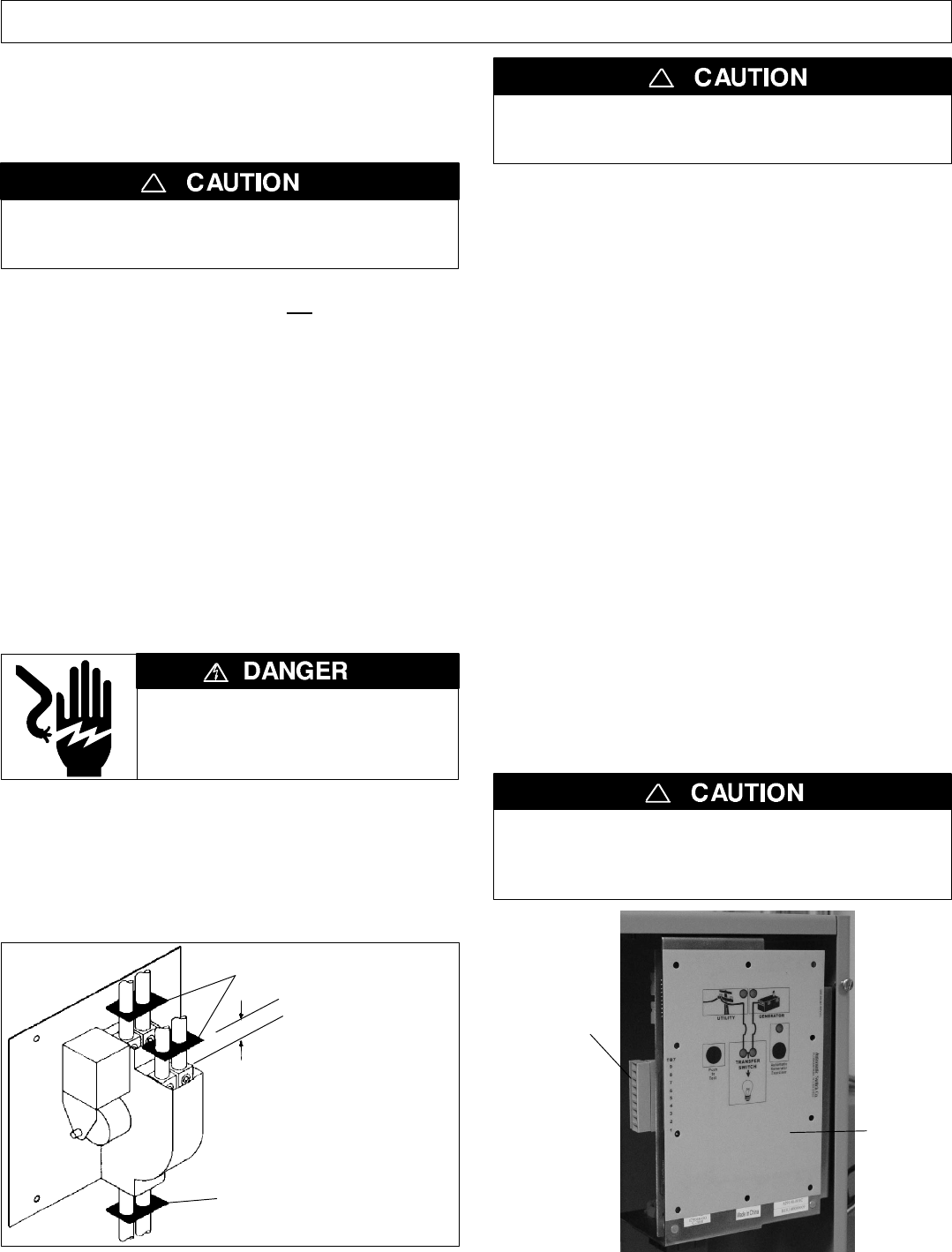
GENERATOR STARTING CONTACTS
Before wiring the generator starting contacts refer to the
generator manufacturer’ s installation manual for require-
ments. Make all connections to the controller with the gen-
erator battery disconnected. Verify that the ignition switch
is in the OFF position. Connect the generator starting con-
tacts to the appropriate terminals on terminal block TB7 on
the Controller (CP). See the wiring diagram provided with
the unit.
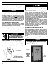
F or wiring convenience terminal block TB7 has a removable
plug. Reconnect the plug with t ermi nal screws f aci ng inward.
CONTROLLER DAMAGE. Observe polarity when
connecting the generator battery to the controller.
Refer to wiring d iagram. Be sure to reinstall the
TB7 block with terminal screws facing inward.
!
digital
controller
removable
terminal
block TB7
Be sure to
reinstall
with
terminal
screws
facing
inward.