8
TROUBLESHOOTING
This troublesho oti ng guide describes some of the si mpl e
causes of proble ms with the install ati o n of the automatic
transfer sw itch. Troubles h ooting beyond the scope o f this
guide s hould n ot b e attempted by t he installer. Alicensed
electric ian must perform al l internal troubl esho oting. ASCO
can be contacted a t 800–937–A SCO or www.asco.com.
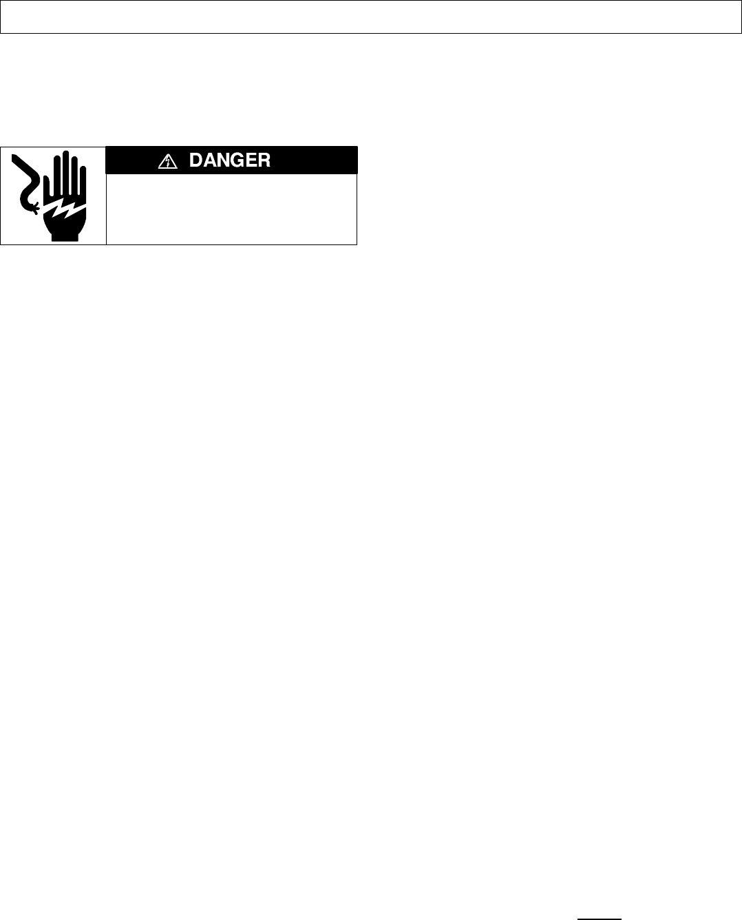
ELECTROCUTION – FLASH HAZARD
Do not w ork o n the t ransfer switch
until both the utility and generator are
off. Turn OFF both cir c uit break er s .
Problem 1
The UTILITY acceptable light does not come on when utility
power is connected to the automatic transfer switch.
● Verify that the utility feed is 240 V ac nominal and 60 Hz.
● Verify that the utility feed is wired to the terminal lugs on
the bottom of the transfer switch marked L1 and L5.
● Verify that the utility feed is connect ed and that its circuit
breaker is ON.
● With ALL POWER OFF, verify that the transfer switch
harness is connected properly to the controller (plug at
the bottom).
Problem 2
Power is connected (UTILITY acceptable lig ht a nd/or
GENERATOR acceptable lights are on) but both
TRANSFER SWITCH position lights are off.
● With ALL POWER OFF, verify that the transfer switch
harness is connected properly to the controller (plug at
the bottom).
Problem 3
Generator does not crank when the utility source fails or
when the Push to Test button is pressed.
● Verify that the generator starting controls are set for
automatic operation.
● Verify engine start low voltage wiring betw een controller
terminal block TB7 (plug on the left) and the generator.
Check that TB7 plugis properly seated in TB7 receptacle.
● Verify that the generator battery is connected and that the
battery volt age meets the generator manufacturer’s
recommendation.
● Verify that the correct contact (normally open or normally
closed) is being utilized (see the generator manual).
Problem 4
Generator cranks but does not start when the utility source
fails or when the Push to Test button is pressed.
● Verify engine start low voltage wiring betw een controller
terminal block TB7 (plug on the left) and the generator.
Check that TB7 plugis properly seated in TB7 receptacle.
● V eri fy proper generato r operatio n (see generator m anual ).
Problem 5
The automatic transfer switch does not t ransfer the load to
the generator (TRANSFER SWITCH on generator light does
not come on).
● V eri fy that the GENERATOR source a cceptable light is on.
The transfer switc h wil l n ot retransfer the l o ad to the genera-
tor until the generator output is acceptable. If the light is off
verify that the circuit break er for the generator feed is ON.
● Wai t 1 5 seconds. There is a 1 5 second delay a fter the
generator output becomes acceptable to permit the
generator t o warm up.
● If the GENERATOR source acceptable light still does not
come on, see Problems 3 and 4.
Problem 6
The automatic transfer switch does not transfer the load
back to the utility (TRANSFER SWITCH on utility light does
not come on).
● V eri fy that the UTILITY source acceptable light is on. The
transfer sw i tch w i ll not r etransf er the load to the uti l ity until
the utility sourc e is acceptable and the light is on. If light is
off, verify that the circuit breaker from the utility f eed isON.
● Wai t 5 minutes. There i s a 5 minute d el ay on retransfer to
the u ti l ity.
Problem 7
The GENERATOR source acceptable lig ht does n ot g o off
after the automatic transfer switch retransfers the load back
to the utility.
● Wai t 1 m inute. After l o ad retransfer t o t he uti li ty, there is a
1 m i nute d el ay for g enerato r cool down before shut down.
● Verify proper operation of the generator (see the
generator manual).
Problem 8
Both TRANSFER SWITCH position lights are flashing (this
indicates an error condition). *
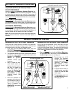
● Count the number of tim es the Automatic Generator
Exer ci se r light fl ashes (repeats after pause). This number
is the error code.
● Error c o des:
2 Generator failed to start. See P ro bl ems 3 and 4 .
3 Generator failed after starting. See generator manual .
4 Generator over frequency. See g enerator manual.
5 Transfer Switch d id not transfer the load
to the generator. Service required.
6 Transfer Switch d id not transfer the load
to the utility. Servic e required.
7 Contro ll er e rro r. Service required.
● To cl ear erro r co de, press and release
Push to Te st butto n.
* NOTE: These lights will flash only when c ontroller power
is available from either of the two power sources.


