


13
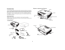
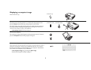
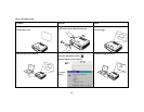
Connecting a video device
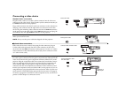
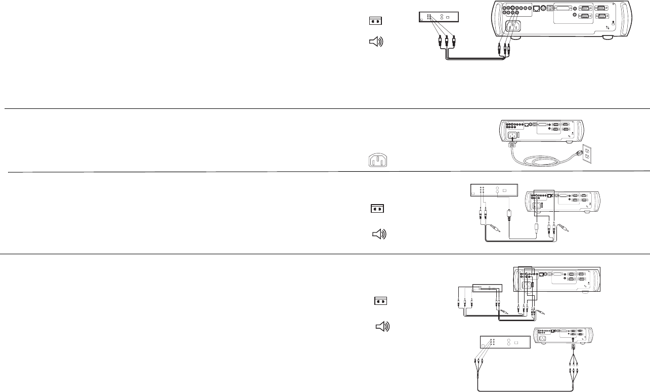
Standard video connections
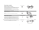
Plug the audio/video (A/V) cable’s yellow connector into the video-out
connector on the video device. Plug the other yellow connector into the yel-
low Video 2 connector on the projector.
Plug a white connector into the left audio out connector on the video device
and plug a red connector into the right audio out connector on the video
device. Plug the remaining white connector into the left audio in connector
on the projector (to the right of the yellow Video 2 connector), and plug the
red connector into the right audio in connector on the projector.
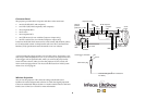
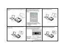
Connect the black power cable to the connector on the back of the projector
and to your electrical outlet.
NOTE: Always use the power cable that shipped with the projector.
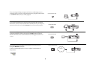
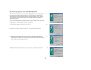
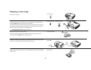
Optional video connections
If the video device uses a round, four-prong S-video connector, plug an
S-video cable (sold separately) into the S-video connector on the video
device and into the Video 1 connector on the projector. Use the A/V cable’s
audio connectors as described directly above (the yellow connectors on the
A/V cable are not used).
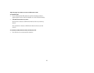
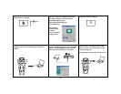
If the video device uses component cable connectors (sold separately), plug
the cable’s green connectors into the green component-out connector on the
video device and into the green component connector (labeled “Y”) on the
projector. Plug the component cable’s blue connectors into the blue compo-
nent-out connector on the video device and into the blue component con-
nector (labeled “Pb”) on the projector. Plug the component cable’s red
connectors into the red component-out connector on the video device and
into the red component connector (labeled “Pr”) on the projector. If you are
using RGB input, plug the additional connector into the Video 2/Synch con-
nector and turn on the RGB Video option in the Sources menu. See page 33.
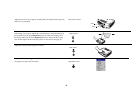
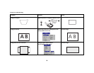
To connect a progressive scan EdTV or HD component source, use the Com-
ponent to VESA adapter to connect the source.
connect A/V cable
computer 2
network
audio in
L
computer in
trigger
monitor out
serial control
R
audio in
computer 1
USB
mouse
computer 3
connect power cable
computer 2
network
audioin
L
computer in
trigger
monitor out
serial control
R
audioin
computer 1
USB
mouse
computer 3
I
O
connect S-video and video cables
computer 2
network
audioin
L
computer in
trigger
monitor out
serial control
R
audioin
computer 1
USB
mouse
computer 3
I
O
connect component cables
I
O
computer 2
network
audioin
L
computer in
trigger
monitor out
serial control
R
audioin
computer 1
USB
mouse
computer 3
and video cables
computer2
network
audioin
L
computerin
trigger
monitorout
serialcontrol
R
audioin
computer1
USB
mouse
computer3
VESA adapter
component to