


2-2 21152 PCI-to-PCI Bridge Evaluation Board
User’s Guide
Installation
2.4 Installation Procedure
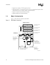
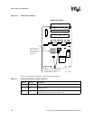
Figure 1-1 illustrates the EB152 and shows the location of components referred to in this section.
Install the EB152 as follows:
1. Power down the host system that will contain the EB152.
2. Place the motherboard with the associated support devices on a bench if mechanical
constraints do not allow testing of the EB152 and the expansion slots inside the system box.
3. Configure your system as follows:
a. Insert the card edge of the EB152 into a PCI slot.
b. Insert a 5-V or universal option PCI card into any or each of the four secondary bus option
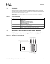
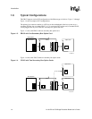
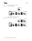
card slots. Section 1.4 shows examples of typical PCI configurations.
4. Power up the system.
5. Verify autoconfiguration of the 21152 and of any devices that are plugged in as follows:
a. Verify that system BIOS or firmware detects and configures the PCI devices downstream
of the 21152. If system BIOS is not available, use the DOS utility provided with the
EB152 kit to configure the devices downstream of the 21152, and verify proper
configuration.
b. Install device drivers for any PCI devices that are downstream the 21152, and verify
proper configuration of those devices.
6. If desired, monitor bridge secondary PCI control signals by connecting a logic analyzer to
pods J2 and J8 through J12.