


21152 PCI-to-PCI Bridge Evaluation Board
User’s Guide 3-1
Interrupt Routing
3
This chapter describes the way in which interrupts are routed. This information is provided as a
reference for designers.
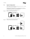
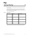
Because a total of 16 interrupts are connected to the secondary bus PCI slots (INTA#, INTB#,
INTC#, and INTD# for each slot) and only four interrupts are driven to the card edge, the 16
incoming interrupts must be combined. This ORing of interrupts is performed in accordance with
the PCI-to-PCI Bridge Architecture Specification.
Table 3-1 shows the ORing of interrupts.
In accordance with the PCI-to-PCI Bridge Architecture Specification, Revision 1.0, interrupts of
the devices on the secondary slots are wire ORed and routed to PCI fingers of the EB152.
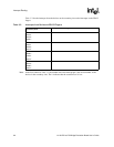
Table 3-1. Interrupt ORing
Device Number Interrupt Pin
on Device
Interrupt Pin
on Board Connector
4 INTA#
INTB#
INTC#
INTD#
INTA#
INTB#
INTC#
INTD#
5 INTA#
INTB#
INTC# I
INTD#
INTB#
INTC#
INTD#
INTA#
6 INTA#
INTB#
INTC#
INTD#
INTC#
INTD#
INTA#
INTB#
7 INTA#
INTB#
INTC#
INTD#
INTD#
INTA#
INTB#
INTC#