


Installations
34
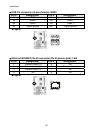
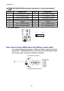
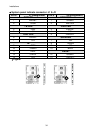
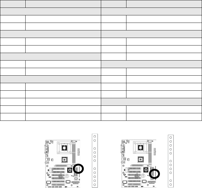
System panel indicate connector: J1 & J2
Pin # J1 Assignment Pin # J2 Assignment
PWR ON KEYLOCK
1 PWRBT- 1 Ground
2 5VSB 2 KBLOCK
TB LED PWR LED
4 GND 3 PWLED-
5 +5V 4 NC
HDD LED
5 PWLED+
6 HDLED-
SPEAKER
7 +5V 7 +5V
IR
8 Ground
9 IRTX 9 NC
10 Ground 10 BEEP
11 IRRX
RESET
12 CIRRX 12 Ground
13 +5V 13 RESET+
y Figure:
J1
J
2