


3-15
HARDWARE OVERVIEW
3
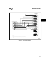
3.8 LCD INTERFACE
The evaluation board includes a 16-character by 1-line LCD display. The display has an 8-bit
interface and is designed to operate at up to 20 MHz. The display includes a Hitachi* 44780 LCD
display controller that takes care of functions such as character interpretation and display refresh.
The display is write-only. This is because the display controller operates at 5 volts V
CC
. A 5-volt
part driving a 3.3-volt bus can damage parts operating at 3.3 volts V
CC
. This means that the
BUSY pin of the processor cannot be monitored to determine when the processor is ready for the
next command, so a delay loop must be used to allow the display to finish commands.
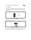
Signals from the 80x186 processor can be connected directly to the LCD controller inputs,
regardless of V
CC
, because 3.3 volt and 5 volt outputs are compatible with 5 volt TTL level
inputs.
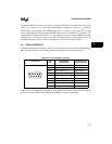
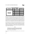
The LCD display is mapped in I/O space at 400H to 440H. All command and data writes to the
display are to this address. Port pin 1.4 is used to control which LCD register is accessed. P1.4 = 0
accesses the command register; P1.4 = 1 accesses the data register.
3.8.1 LCD Interface Demo
The diskette provided in your kit includes a file, LCD_DEMO.ASM, that contains source code
you can assemble and load onto the board (using iECM). You can execute the program for a
demonstration of the basic principals of operating the LCD display module. This program prints
a static message to the display. The source code is commented to serve as a tutorial and can be
adapted as needed for other applications and messages. Note that although the LCD module is
capable of displaying standard ASCII (characters 32 through 125) or custom characters, this
demo uses only ASCII characters.
For more information regarding the operation of the display controller, please refer to the Hitachi
LCD Controller/Driver LSI Data Book.