


Installation Guide for POC Board
2. Verify contents. Inspect the contents of your kit, and ensure that everything listed in
Section 1.3 is included. Check for damage that may have occurred during shipment.
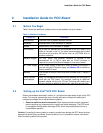
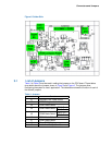
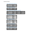
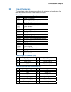
3. Check jumper settings. Verify that the following jumpers are set in their default state
(see Table 3).
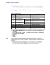
Table 3. Jumper Settings
Jumper Function Default Setting
J1 Compact Flash Power Select 3.3 V : Short 1-2
J2 LVDS Voltage select 3.3 V : Short 1-2
J3 COM1 Mode Select RS-232 : Short 3-5,4-6
CN15 Pin 1
DCD : Short 3-5
J4 COM1 Mode Select
CN15 Pin 8
RI : Short 4-6
CN15 Pin 1 DCD : Short 3-5
J5 COM2 Mode Select
CN15 Pin 8 RI : Short 4-6
J6 COM1 Mode Select RS-232 : Short 3-5,4-6
J7 COM1 Mode Select RS-232 : Short 1-2
J8 Clear CMOS Setting Normal : Short 1-2
J9 Audio Line Out/Speaker Out Line Out : Short 1-3, 2-4
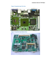
4. Verify installed hardware. Make sure the following hardware is populated on your
POC board:
− One on-board Intel Intel
®
Celeron
®
M Processor Ultra Low Voltage 373 processor in
the 479-ball µFCBGA package
− BIOS FWH
− Battery
− Heatsink
Note: The above hardware should have been correctly installed at the factory. If they are not
installed correctly, DO NOT power on the board. Correctly re-install the components before
proceeding.
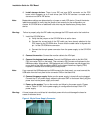
5. Install memory. Install the SODIMM in memory slot DIMM1. Insert the SODIMM
above the slot (the DIMM is keyed so that it only fits in the slot in one orientation).
Firmly, but carefully, insert the SODIMM into the slot until the tabs close.