


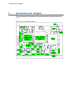
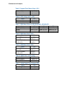
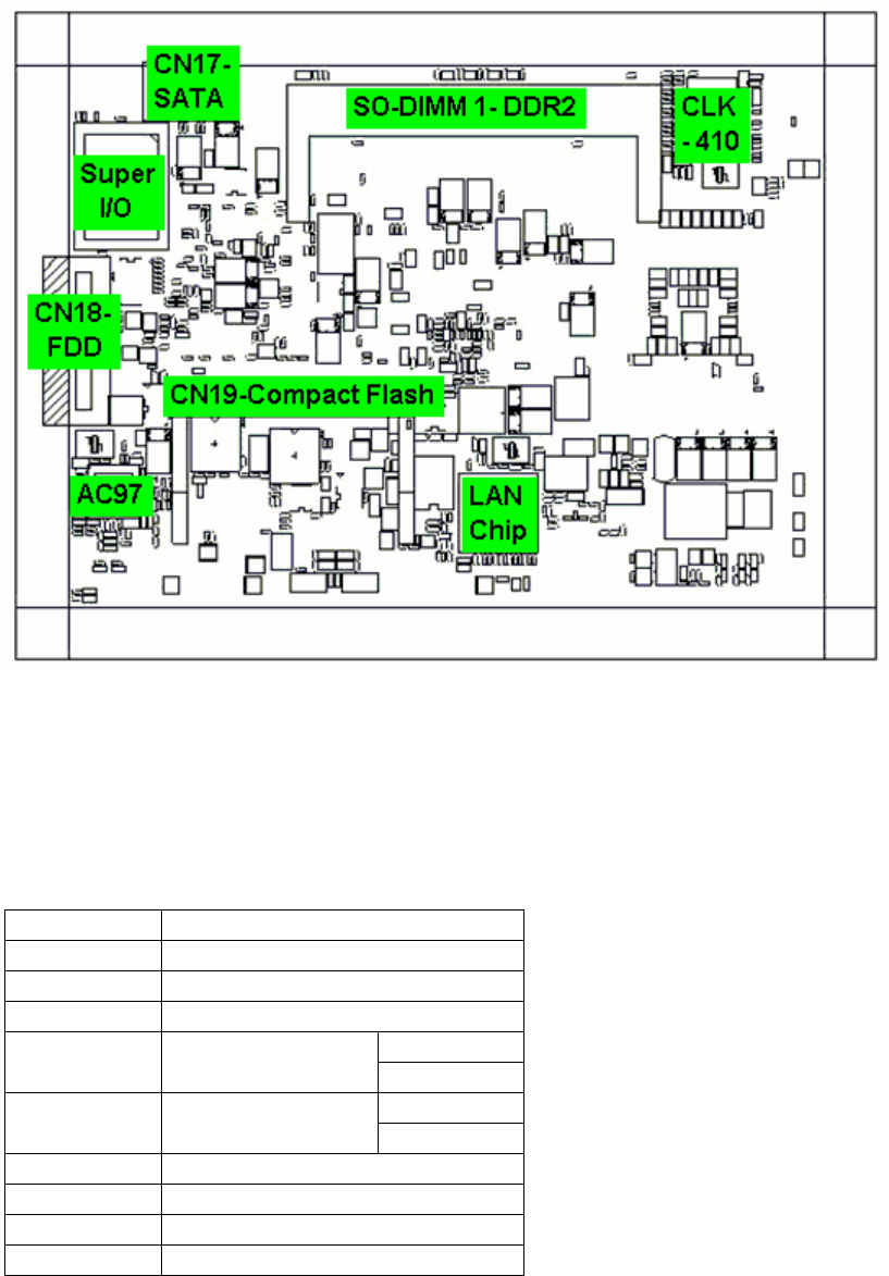
Connectors and Jumpers
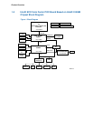
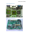
Figure 6. Solder Side
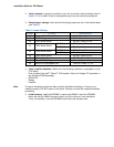
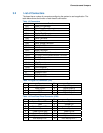
3.1 List of Jumpers
Table 4 to Table 9 must be used in setting the jumpers on the POC board. These tables
give details about the jumpers shown in Figure 5 and Figure 6. The jumpers allow
configuring the system to user’s application. The table below shows the function of each of
the board’s jumpers:
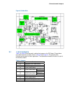
Table 4. Jumpers
Label Function
J1 Compact Flash Power Select
J2 LVDS Voltage select
J3 COM1 Mode Select
CN15 Pin 1
J4 COM1 Mode Select
CN15 Pin 8
CN15 Pin 1
J5 COM2 Mode Select
CN15 Pin 8
J6 COM1 Mode Select
J7 COM1 Mode Select
J8 Clear CMOS Setting
J9 Audio Line Out/Speaker Out