


Chapter 3 Software Configuration
Page:3-8
PCI-471LF USER
′
S MANUAL
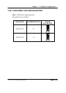
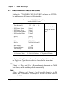
3-7. WATCHDOG TIMER CONFIGURATION
The I/O port address of the watchdog timer is 2E(hex) and 2F(hex). 2E (hex) is the
address port. 2F(hex) is the data port. User must first assign the address of register by
writing address value into address port 2E(hex), then write/read data to/from the
assigned register through data port 2F (hex).
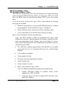
Configuration Sequence
To program W83627HF configuration registers, the following configuration sequence
must be followed:
(1) Enter the extended function mode
(2) Configure the configuration registers
(3) Exit the extended function mode
(1) Enter the extended function mode
To place the chip into the extended function mode, two successive writes of 0x87
must be applied to Extended Function Enable Registers (EFERs, i.e. 2Eh).
(2) Configurate the configuration registers
The chip selects the logical device and activates the desired logical devices through
Extended Function Index Register (EFIR) and Extended Function Data Register
(EFDR). EFIR is located at the same address as EFER, and EFDR is located at
address (EFIR+1).
First, write the Logical Device Number (i.e.,0x07) to the EFIR and then write the
number of the desired logical device to the EFDR. Secondly, write the address of the
desired configuration register within the logical device to the EFIR and then write (or
read) the desired configuration register through EFDR.
(3) Exit the extended function mode
To exit the extended function mode, one write of 0xAA to EFER is required. Once
the chip exits the extended function mode.
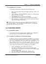
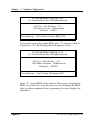
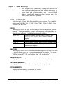
Example Program
1. Enable watchdog timer and set 30 sec. as timeout interval
;-----------------------------------------------------------
Mov dx, 2eh ; Enter to extended function mode
Mov al, 87h
Out dx, al
Out dx, al
;-----------------------------------------------------------