


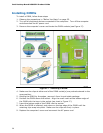
Installing and Replacing Desktop Board Components
43
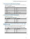
Connecting to the HD Audio Link Header
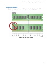
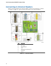
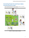
See Figure 22, A for the location of the HD Audio Link header. Table 4 shows the pin
assignments for the header.
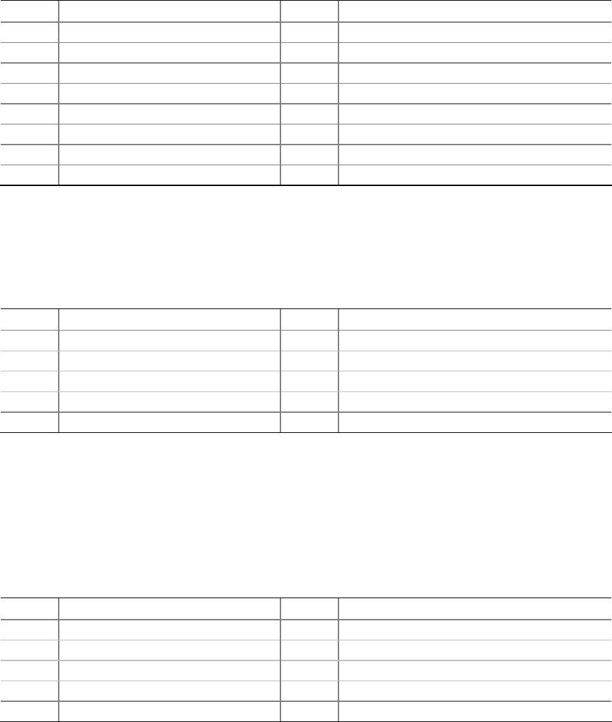
Table 4. High Definition Audio Link
Pin Signal Name Pin Signal Name
1 BCLK 2 Ground
3 RST 4 3.3V/1.5V I/O
5 SYNC 6 Ground
7 SDO 8 3.3V_Core
9 SDI 10 +12V
11 No Connection 12 Key
13 No Connection 14 3.3V/1.5V STBY
15 No Connection 16 Ground
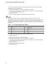
Connecting to the IEEE 1394a Header
See Figure 22, B for the location of the blue IEEE 1394a header. Table 5 shows the
pin assignments for the header.
Table 5. IEEE 1394a Signal Header Names
Pin Signal Name Pin Signal Name
1 TPA1+ 2 TPA1-
3 Ground 4 Ground
5 TPA2+ 6 TPA2-
7 +12 V 8 +12 V
9 Key (no pin) 10 Ground
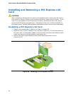
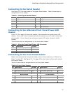
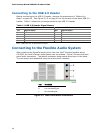
Installing a Front Panel Audio Solution for Intel
®
High
Definition Audio
Figure 22, C on page 42 shows the location of the yellow front panel audio header.
Table 6 shows the pin assignments for the front panel audio header.
Table 6. Front Panel Audio Header Signal Names for Intel High Definition
Audio
Pin Signal Name Pin Signal Name
1 PORT 1L 2 GND
3 PORT 1R 4 PRESENCE#
5 PORT 2R 6 SENSE1_RETURN
7 SENSE_SEND 8 KEY (no pin)
9 PORT 2L 10 SENSE2_RETURN