


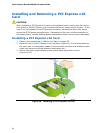
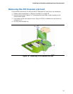

Installing and Replacing Desktop Board Components
45
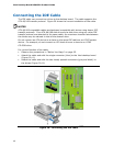
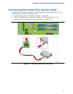
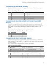
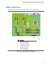
Connecting to the Serial Header
See Figure 22, D for the location of the green Serial header. Table 8 shows the pin
assignments for the header.
Table 8. Serial Signal Header Names
Pin Signal Name Pin Signal Name
1 DCD 2 RXD#
3 TXD# 4 DTR
5 Ground 6 DSR
7 RTS 8 CTS
9 RI 10 No Connection
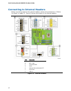
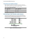
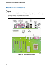
Connecting to the Alternate Front Panel Power LED
Header
Figure 22, E on page 42 shows the location of the alternate front panel power LED
header. Pins 1 and 3 of this header duplicate the signals on pins 2 and 4 of the front
panel header. If your chassis has a three-pin power LED cable, connect it to this
header.
Table 9 shows the pin assignments for the front panel header.
Table 9. Alternate Front Panel Power LED Connector
Pin Description In/Out
1 Front panel green LED Out
2 No pin
3 Front panel yellow LED Out
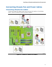
Connecting to the Front Panel Header
Before connecting to the front panel header, observe the precautions in "Before You
Begin" on page
25. See Figure 22, F on page 42 for the location of the multi-colored
front panel header.
Table 10 shows the pin assignments for the front panel header.
Table 10. Front Panel Header
Pin Description In/Out
Pin Description In/Out
Hard Drive Activity LED Power LED
1 Hard disk LED pull-up to +5 V
Out 2 Front panel green LED Out
3 Hard disk active LED Out 4 Front panel yellow LED Out
Reset Switch On/Off Switch
5 Ground 6 Power switch In
7 Reset switch In 8 Ground
Power Not Connected
9 Power Out 10 No pin