


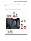

Installing and Replacing Desktop Board Components
49
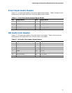
Chassis Intrusion Header
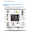
Figure 27, E shows the location of the chassis intrusion header. This header can be
connected to a mechanical switch on the chassis to detect if the chassis cover is
removed.
Table 8 shows the pin assignments and
signal names for the chassis intrusion header.
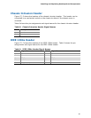
Table 8. Chassis Intrusion Header Signal Names
Pin Description
1 Intruder
2 Ground
IEEE 1394a Header
Figure 27, F shows the location of the IEEE 1394a header. Table 9 shows the pin
assignments and signal names for the IEEE 1394a header.
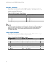
Table 9. IEEE 1394a Header Signal Names
Pin Signal Name Pin Signal Name
1 TPA1+ 2 TPA1-
3 Ground 4 Ground
5 TPA2+ 6 TPA2-
7 +12 V 8 +12 V
9 Key (no pin) 10 Ground