


Installing and Replacing Desktop Board Components
55
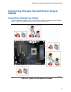
1. Observe the precautions in "Before You Begin" on page 27.
2. Connect the 12 V processor core voltage power supply cable to the 2 x 4 pin
connector.
3. Connect the main power supply cable to the 2 x 12 pin connector.
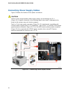
4. If additional power is required, connect the appropriate power supply cable to
either the 1 x 4 auxiliary PCI Express graphics power connector or to the SATA-
style auxiliary PCI Express graphics power connector or to both.
Setting the BIOS Configuration Jumper
NOTE
Always turn off the power and unplug the power cord from the computer before
moving the jumper. Moving the jumper with the power on may result in unreliable
computer operation.
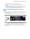
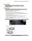
Figure 31 shows the location of the Desktop Board’s BIOS confi
guration jumper block.
Figure 31. Location of the BIOS Configuration Jumper Block
The three-pin BIOS jumper block enables all board configurations to be done in the
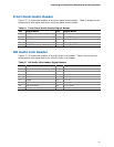
BIOS Setup program. Table 14 shows the jumper setti
ngs for the BIOS Setup
program modes.